2 Rockwell Automation Publication 440R-IN088A-EN-P - July 2022
Minotaur MSR138DP, MSR138.1DP Monitoring Safety Relay Installation Instructions
Diagnostics
The solid-state status signal Y35 indicates the safety input state. The solid-state
status output Y32 and the auxiliary (N.C.) output 41-42 signals the safety output
state.
Safety Input
One safety device can be monitored per unit. According to the wiring inputs,
cross-loop monitoring of the inputs is enabled or disabled. You can enable
cross-loop monitoring for 2-channel safety inputs in 4-wire connection (S11-S12,
S21-S22). Cross-loop monitoring is disabled for single-channel inputs, dual-channel
inputs in 3-wire connection, and 24V DC signals. For external 24V DC signals, the
negative pole must connect to S21.
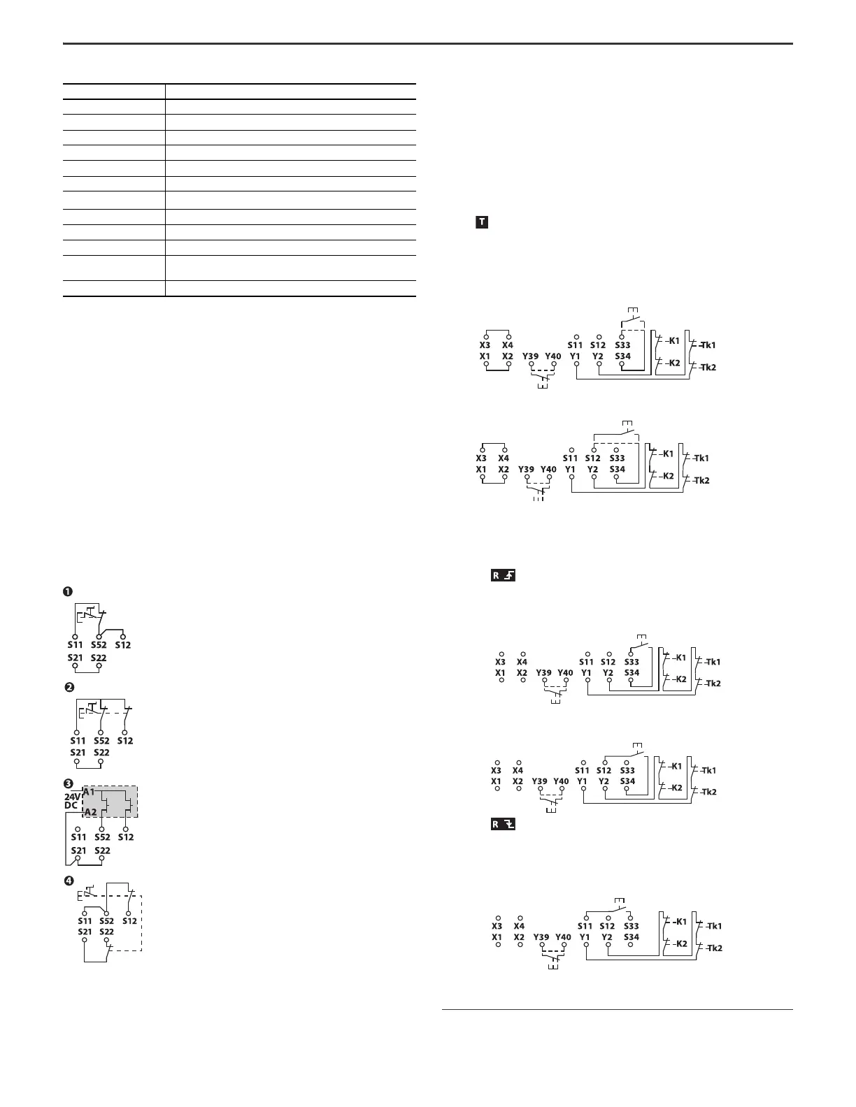
Reset
• Reset modes - The reset mode is configurable for automatic/manual start
and manual monitored reset (MSRxxxRT).
A valid start/reset can only operate if the feedback circuit (Y1-Y2) and the
time-reset circuit (Y39-Y40) are closed. Feedback contacts (N.C.) of
controlled actuators connect to Y1-Y2. Start/reset during the time lapse
causes a fault state. To avoid a lockout condition by start/reset, the N.C.
contacts (55-56) of the MSR138.1 safety relay connect in series with the
feedback circuit Y1-Y2.
• T - Automatic/manual start
(a)
In Automatic/Manual Start mode, the reset circuit S33-S34 is not
monitored against signal changes (no edge detection). The safety relay is
active once the safety inputs and the reset circuit close. If the safety
inputs and reset circuit concurrently close during power-up, the safety
relay activates immediately.
• R - Manual monitored reset
(b)
In Manual Monitored Reset mode, a signal change of the reset circuit
(S33-S34) is required and monitored. A reset fault occurs if the safety
inputs remain open while the reset circuit is closed.
- Positive edge:
The safety relay is active once the safety inputs close and then the
reset circuit is closed.
- Negative edge (440R-xxxxxM):
The safety relay is active once the safety inputs close and then the
reset circuit closes and releases again. The circuit resets upon release
of the Reset button.
For both methods, the MSR138/.1DP safety relay is suitable for the safety
requirements according to EN/ISO 13849-1.
Installation group Overvoltage category III, VDE 0110-1
Operating temperature -5…+55 °C (23…131 °F)
Relative Humidity 90%
Enclosure protection IP40 (NEMA 1)
Terminal protection IP20
Wiring Use copper that withstands 60/75 °C (140/167 °F)
Conductor size
0.2...2.5 mm
2
(24…12 AWG)
Torque settings Terminal screws: 0.6…0.8 N•m (5…7 lb•in)
Case material Polyamide PA 6.6
Mounting 35 mm (1.38 in.) DIN rail in enclosure to a minimum of IP54
Weight
24V AC/DC: 350 g (0.77 lb)
115V AC or 230V AC: 490 g (1.08 lb)
Vibration 10…55 Hz, 0.35 mm (0.01 in.)
(1) Operation time (day, hour)
(2) Cycle time (hour, sec)
Max PLc: 1-CH
(1)
; N.C.
(1) 1-CH = Single-channel
Max PLd: 2-CH
(2)
; 3-wire connection
(2) 2-CH = Dual-channel
Max PLe: 2-CH
(2)
; 24V DC signal
Max PLe: 2-CH
(2)
; 4-wire connection, cross
faults require fault reset
Table 1 - Technical Specifications (Continued)
Attribute Value
(a) T = Jumper X1-X2, X3-X4
(b) R = No jumper
MSRxxxT
MSRxxxT
440R-xxxxxM
MSRxxxR
MSRxxxR
440R-xxxxxM

 Loading...


