English-15
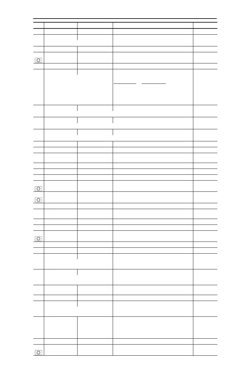
A079 [Jog Accel/Decel] 0.1/600.0 Secs 0.1 Secs 10.0 Secs
A080 [DC Brake Time] 0.0/99.9 Secs 0.1 Secs 0.0 Secs
A setting of 99.9 Secs = Continuous
A081 [DC Brake Level] 0.0/(Drive Amps × 1.8) 0.1 Amps Amps × 0.05
A082 [DB Resistor Sel] 0/99 0 = “Disabled”
1 = “Normal RA Res”
2 = “NoProtection”
3-99 = % of Duty Cycle
0
A083 [S Curve %] 0/100% 1% 0% (Disabled)
A084 [Boost Select] 0/14 Settings in % of base voltage. 8
7 4-11 kW
(5-15 HP)
Only active when A125 [Torque Perf Mode] is
set to 0 “V/Hz”.
0 = “Custom V/Hz”
Var iable Tor que
Constant Torque
1 = “30.0, VT” 5 = “0.0, no IR” 10 = “10.0, CT”
2 = “35.0, VT” 6 = “0.0” 11 = “12.5, CT”
3 = “40.0, VT” 7 = “2.5, CT” 12 = “15.0, CT”
4 = “45.0, VT” 8 = “5.0, CT” 13 = “17.5, CT”
9 = “7.5, CT” 14 = “20.0, CT”
A085
[Start Boost] 0.0/25.0%
0.1% 2.5%
Only active when A084 [Boost Select] and A125 [Torque Perf Mode] are set to “0”.
A086
[Break Voltage] 0.0/100.0%
0.1% 25.0%
Only active when A084 [Boost Select] and A125 [Torque Perf Mode] are set to “0”.
A087
[Break Frequency] 0.0/400.0 Hz
0.1 Hz 15.0 Hz
Only active when A084 [Boost Select] and A125 [Torque Perf Mode] are set to “0”.
A088 [Maximum Voltage] 20/Rated Volts 1 VAC Rated Volts
A089 [Current Limit 1] 0.1/(Drive Amps × 1.8) 0.1 Amps Amps × 1.5
A090 [Motor OL Select] 0/2 0 = “No Derate” 1 = “Min Derate”
2 = “Max Derate”
0
A091 [PWM Frequency] 2.0/16.0 kHz 0.1 kHz 4.0 kHz
A092 [Auto Rstrt Tries] 0/9 1 0
A093 [Auto Rstrt Delay] 0.0/300.0 Secs 0.1 Secs 1.0 Secs
A094 [Start At PowerUp] 0/1 0 = “Disabled” 1 = “Enabled” 0
A095 [Reverse Disable] 0/1 0 = “Rev Enabled” 1 = “Rev Disabled” 0
A096 [Flying Start En] 0/1 0 = “Disabled” 1 = “Enabled” 0
A097 [Compensation] 0/3 0 = “Disabled”
1 = “Electrical”
2 = “Mechanical”
3 = “Both”
1
A098 [SW Current Trip] 0.0/(Drive Amps × 2) 0.1 Amps 0.0 (Disabled)
A099 [Process Factor] 0.1/999.9 0.1 30.0
A100 [Fault Clear] 0/2 0 = “Ready/Idle” 1 = “Reset Fault”
2 = “Clear Buffer”
0
A101 [Program Lock] 0/9999 0 = “Unlocked” 1 = “Locked” 0
A102 [Testpoint Sel] 0/FFFF 1 Hex 400
A103 [Comm Data Rate] 0/5 0 = “1200”
1 = “2400”
2 = “4800”
3 = “9600”
4 = “19.2K”
5 = “38.4K”
3
Power to drive must be cycled before any
changes will affect drive operation.
A104 [Comm Node Addr] 1/247 1 100
Power to drive must be cycled before any
changes will affect drive operation.
A105 [Comm Loss Action] 0/3 0 = “Fault”
1 = “Coast Stop”
2 = “Stop”
3 = “Continu Last”
0
A106 [Comm Loss Time] 0.1/60.0 Secs 0.1 Secs 5.0 Secs
A107 [Comm Format] 0/5 0 = “RTU 8-N-1”
1 = “RTU 8-E-1”
2 = “RTU 8-O-1”
3 = “RTU 8-N-2”
4 = “RTU 8-E-2”
5 = “RTU 8-O-2”
0
Power to drive must be cycled before any
changes will affect drive operation.
A108 [Language] 1/10 1 = “English”
2 = “Français”
3 = “Español”
4 = “Italiano”
5 = “Deutsch”
6 = “Reserved”
7 = “Português”
8 = “Reserved”
9 = “Reserved”
10 = “Nederlands”
1
A109 [Anlg Out Setpt] 0.0/100.0% 0.1% 0.0%
A110 [Anlg In 0-10V Lo] 0.0/100.0% 0.1% 0.0%
No. Parameter Min/Max Display/Options Default
See the PowerFlex 40 User Manual on CD for more information on parameters.

 Loading...


