11
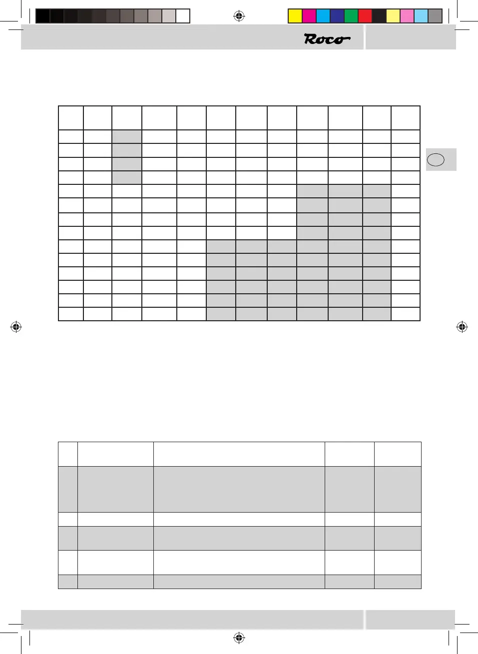
Function Mapping
The function keys on the control device can be allocated to the function outputs of the decoder as required.
The allocation of function keys to function outputs necessitates the carrying out of programming in the
following CVs using the values specied in the table.
CV Key AUX7 AUX6 AUX5 AUX4 AUX3 AUX2 AUX1 Rear
light
Front
light
Value
33 F0v 128 64 32 16 8 4 2 1 1
34 F0r 128 64 32 16 8 4 2 1 2
35 F1 128 64 32 16 8 4 2 1 4
36 F2 128 64 32 16 8 4 2 1 8
37 F3 32 16 8 4 2 1 2
38 F4 32 16 8 4 2 1 4
39 F5 32 16 8 4 2 1 8
40 F6 32 16 8 4 2 1 16
41 F7 4 2 1 4
42 F8 4 2 1 8
43 F9 4 2 1 16
44 F10 4 2 1 32
45 F11 4 2 1 64
46 F12 4 2 1 128
Caution: no allocations are possible in the grey areas.
The bold gures in the table are the works settings which you will also nd in the right-hand column. You
can set the allocations according to your wishes by changing the values in the CVs. Examples: With CV38=6
(i.e. 4+2) results in AUX3 and AUX4 being switched simultaneously with F4. Please refer to the documents
for your locomotive in order to determine which electrical consumers are connected where. If a locomotive
should be supplied with this decoder, it is possible that a customized function mapping could exist which
deviates from the above table.
CV-Liste
CV Name Description Value
Range
Works
Value
1 Locomotive address Address of the locomotive DCC
01 – 127
Motorola
3)
01 – 80
3
2 Start-up voltage Determines the slowest locomotive speed 01 – 255 4
3 Acceleration time The higher this value, the more time the loco-
motive takes to accelerate
01 – 255 6
4 Braking deceleration The higher this value, the more time the loco-
motive takes to brake
01 – 255 2
5 Maximum voltage Determines the fastest locomotive speed 01 – 255 252
8010884920 V_2013.indd 11 07.03.2013 11:56:09