12
The use of this decoder in other than the previously listed digital systems or in power units
which are not factory-equipped with NMRA or NEM (see above) conforming decoder
interfaces (installation by e.g. cutting the interface plug and soldering of the decoder
into the locomotive) can cause irreparable damage to the decoder or the locomotive.
ROCO cannot be held liable in such events for the decoder or the locomotive or any
guarantee. Damage caused by any other changes to the decoder (e.g. applying paint) are
also excluded from any guaranties.
The use of 12 volt bulbs during digital operation can cause irreparable damage (melting)
to the locomotive housing!
Installed 12 volt bulbs must be changed to 16 volt bulbs (already installed in locomotives starting
with fabrication year 2000). 16 volt bulbs can be obtained through stockists or our service
department. Compare with the installed bulb shown in the locomotive replacement parts listing:
art.no. 108616: bulb with attached leads, white 16 V replaces art.no. 93520 12 V
art.no. 109918: bulb with attached leads, red (only 16 volt version)
art.no. 109088: plug-in bulb, small 16 V, replaces art.no. 93518 12 V
art.no. 93734: tubular bulb 16 V, replaces art.no. 93517 12 V
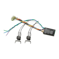
Installation (required only if decoder was bought separately)
Take precautions to protect against hazardous static discharges. If you have ESD (electro-
static discharge) equipment available, then use it. Otherwise make sure that you do not
touch the pins on the connector!
All installation work must be done on vehicles removed from the track. The locomotive must be
in perfect electrical and mechanical condition. Parts subject to wear e.g. motor brushes, wheel
contacts, have to be cleaned or replaced!
Please note the installation instructions provided with all ROCO locomotives having decoder
interfaces !
We recommend, in addition to the specific locomotive installation instructions, the following
procedure:
1. Remove housing and detach the reversing module or the already installed decoder from the
interface.
2. Insert the decoder plug into the interface so that side of the decoder plug with red/orange wire
at the side of the interface marked with + or ✭ (polarity according to NMRA/NEM rules, i.e.
the locomotive moves with the driver’s cab no.1 facing forward).
3. Install the decoder in a suitable location within the locomotive. No part of the decoder must
be touching metal parts of the locomotive! If necessary the location of the decoder must be
insulated with insulation tape to protect the decoder. The insulation must be attached to the
metal parts of the locomotive, but NOT to the decoder (e.g. by winding the insulation tape
around the decoder!). This could lead to failure of the decoder due to overheating. Damage
claims caused by such failures cannot be acceptet!
The factory used heat shrink tubing around the decoder ensures a sucient heat dissipation
and should not be removed.
4. If necessary the decoder can be secured in the desired location with double-sided tape.
8040411920 VI_2013.indd 12 19.06.2013 12:42:18
 Loading...