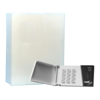
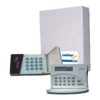
Cerber
®
C41V1/Cerber
®
C41V4
HOOKUP INSTALLATION & PROGRAMMING BOOK
7
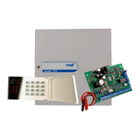
CONNECTORS
The following connectors are located on the PCB panel :
AUX - , AUX +
Connectors for auxiliary power supply.
These terminals supply power for keypads, PIR detectors and other active
devices in the system.
The maximum load on these terminals cannot exceed 500mA. Observe
polarity!
YEL, GRN
Keypad communication.
PGM 1, PGM 2
Programmable "open collector" outputs with negative trigger. The maximum
load on this terminals cannot exceed 100mA.
BELL +, BELL -
Siren output. "BELL+" is a positive trigger output (PNP).
The maximum load on these terminals cannot exceed 1A. Observe polar-
ity!
Z1, COM, Z2, Z3, COM, Z4
Terminals for fully programmable zones.
If not used, the terminals will be closed with a 2K2 EOL resistor.
KEY
Terminals for special Keyswitch/Tamper zones.
If not used, the terminals will be closed with a 2K2 EOL resistor
SET
Phone set.
LINE
Phone line.
DIF
These terminals are used to connect a mini speaker in case of one's wish to
listen to the recorded messages.
 Loading...