EN
40
4.1 Electrical connections
DESCRIPTION
FUSE
N L
Mains power supply 230 Vac ±10% connection. (B70/2DC115/BOX: 115 Vac ± 10%
,^
Fuse 5x20 T1A.
POWER IN
-+
Power feed input from transformer (or from B71/BC battery charger, if used).
N.B.6IEH][MVIHMRJEGXSV]F]63+)68)',2303+=
X-Y-Z
Y
X
M
Z
'SRRIGXMSRXS63+)6FVYWLPIWW13836.
Warning! If the motor rotates in the wrong direction, simply swap any two of the three
motor connectors.
'LIGOXLIGSRRIGXMSRWMPPYWXVEXIHMRƼK
Z-Y-X
Y
Z
M
X
'SRRIGXMSRXS63+)6FVYWLPIWW13836.
Warning! If the motor rotates in the wrong direction, simply swap any two of the three
motor connectors.
'LIGOXLIGSRRIGXMSRWMPPYWXVEXIHMRƼK
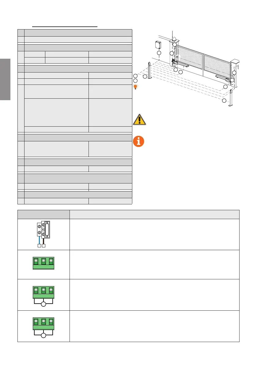
CONNECTING CONTROL UNIT TO MAINS ELECTRICITY
2
2
1
3
4
4
6
9
7
8
3
5
It is the installer's responsibility to verify the
adequacy of the cables in relation to the devices
used in the installation and their technical characteristics.
SUGGESTIONS: in the case of a new installation,
we recommend using cables with a cross section
of 3x2.5 mm
2
and not exceeding 10 m in length to con
nect the motor with the control unit.
With existing installations, we recommend checking
the cross section of the cables and that the cables
themselves are in good condition. Old cables or previous
generation cables, especially if with a cross section of
3x1.5mm
2
, may impair the performance of the digital
brushless motor.
1 Power supply 230 Vac ±10% (115 Vac ±10%)
CONNECTING CONTROL PANEL TO MOTORS
2
Motor 1 3x2,5 mm² (max 10 m) 3x4 mm² (max 30 m)
Motor 2 3x2,5 mm² (max 10 m) 3x4 mm² (max 30 m)
CONNECTING CONTROL PANEL TO ACCESSORIES
3 4LSXSGIPPW6IGIMZIV F4ES/F4S 5x0,5 mm² (max 20 m)
4 4LSXSGIPPW8VERWQMXXIV F4ES/F4S 3x0,5 mm² (max 20 m)
5
Keypad H85/TDS - H85/TTD
(connecting to H85/DEC - H85/DEC2)
2x0,5 mm² (max 30 m)
H85/DEC - H85/DEC2
(connecting to control unit)
4x0,5 mm
2
(max 20 m)
The number of
conductors increases
when using more than
one output contact on
,()',()'
Key selector R85/60 3x0,5 mm² (max 20 m)
CONNECTING CONTROL PANEL TO FLASHING LIGHT
6
LED Flashing light
R92LED24 - FIFTHY/24
Power supply 24Vdc
2x1 mm² (max 10 m)
CONNECTING CONTROL PANEL TO GATE OPEN INDICATOR
7 Power supply 24 Vdc (3 W max) 2x0,5 mm² (max 20 m)
CONNECTING CONTROL PANEL TO COURTESY LIGHT (PURE
CONTACT)
8 Power supply 230 Vac (100 W max) 2x1 mm² (max 20 m)
CONNECTING CONTROL PANEL TO ANTENNA
9 'EFPIX]TI6+ max 10 m