13
Serie BH30
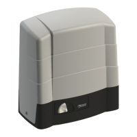
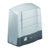
INSTALLAZIONE DELL’ATTUATORE
Togliereilcoperchioslandoloversol’altocomeindicatoing.1.
Comeindicatoing.2,
inseriregliO-Ring(B)suciascunadellevitiM10x40(A);inserirelevitisuiforipostiagliangolidellascoccadelmotoriduttore(C)ebloccarleconidadiM10(D)da
incastrare sotto al motoriduttore.
Posizionarel’attuatorenei4tiranti.Senecessarioèpossibiletogliereidadisullasuperciedellapiastradifondazione.Allinearel’attuatoreconlacremaglierasia
orizzontalmentecheverticalmente.Raggiuntalaposizionecorrettastringereconunachiavessada17idadidissaggiodaM10.Vericatoilcorrettoaccoppiamentoconla
cremagliera in tutta la sua corsa inserire il coperchio.
INSTALLATION OF THE ACTUATOR
Removethecover,drawingitupwardsasshowning.1.
Asshowning.2,
PuttheO-rings(B)ontoeachoftheM10x40screws(A);
Insert the screws into the holes at the corners of the gearmotor shell (C) and secure them with the M10 nuts (D) under the gearmotor.
Positiontheactuatoronthe4tierods.Ifnecessarythenutsonthesurfaceofthefoundationplatemayberemoved.Aligntheactuatorwiththerackbothhorizontallyand
vertically. When the correct position has been reached, use one 17 box wrench to tighten the M10 nuts. Having checked that engagement along the whole length of the rack
is correct, insert the cover.
INSTALLATION DES ANTRIEBS
Den Deckel entfernen, wie auf Abb. 1 gezeigt, nach oben herausziehen.
Wie auf Abb. 2 dargestellt,
VersehenSiealleSchraubenM10x40(A)mitO-Ringen(B).SteckenSiedieSchraubenindieBohrungenandenEckendesGehäusesdesGetriebemotors(C)
undschraubenSiedieMutternM10(D),dieunterhalbdesGetriebemotorseinsetztwerdenmüssen,auf.
DenGetriebemotor,aufdie4Zugstäbeaufsetzen.
Wennerforderlich,könnendieMutternanderOberseitederGrundplatteentferntwerden.DenAntriebsowohlsenkrechtalsauchwaagrechtnachderZahnstangeausrichten.
NachdemdiekorrektePositionerzieltwurde,mitein17erMaulschlüsseldieMutternundM10festziehen.DaskorrekteGreifenindieZahnstangeüberdiegesamteLänge
sicherstellen und denDeckelwiederschließen.
INSTALLATION DE L’ACTIONNEUR
Enlever le couvercleenleretiréverslehautcommeindiquésurlag.1
Commeindiquésurlag.2,
insérerlesjointsO-Ring(B)surchacunedesvisM10x40(A);insérerlesvisdanslestroussituésdanslesanglesdelacoquedumotoréducteur(C)etles
bloquer avec les écrous M8 (D) à encastrer sous le motoréducteur.
Positionnerl’actionneurdansles4tirants.Sicelaestnécessaire,ilestpossibled’enleverlesécroussetrouvant
surledessusdelaplaquedefondation.Alignerl’actionneuràlacrémaillèreaussibienhorizontalementqueverticalement.Unefoislapositioncorrecteobtenue,serrer,avec
unecléxesde17,lesécrousdexationdeM10Contrôlerl’assemblageaveclacrémaillèresurtoutesacourse.Replacer que le couvercle.
INSTALACIÓN DEL SERVOMOTOR
Quite el tapónextrayéndolohaciaarriba,comosemuestraenlag.1.
Comoseilustraenlag.2,
colocarlasjuntastóricas(B)encadaunodelostornillosM10x40(A);insertarlostornillosenlosagujerosenlasesquinasdelcuerpomotor(C)yasegurarloscon
tuercasM10(D)paraencajardebajodelmotor.
Coloqueelservomotorenlos4tirantes.Siesnecesario,esposiblequitarlastuercasqueseencuentranenlasuperciedela
losadecimentación.Alineeelservomotorconlacremallera,tantohorizontalcomoverticalmente.Unavezobtenidalaposicióncorrecta,apriete,conunallavejasde17,las
tuercasdejacióndeM10.Trascontrolarelcorrectoacoplamientoconlacremalleraentodasucarrera,cierre el tapón.
INSTALAÇÃO DO ACTUADOR
Retire a tampapuxando-asparacimaconformeilustraag.1
Conformeilustraag.2,
introduzirasjuntascirculares(B)emcadaumdosparafusosM10x40(A);introduzirosparafusosnosfurosquehánoscantosdacaixadomotorredutor(C)e
prendê-los com as porcas M10 (D) que se encaixam em baixo do motorredutor.
Posicioneoactuadornos4tirantesSenecessário,épossívelretirarasporcasdasuperfícieda
chapadefundação.Alinheoactuadorcomacremalheiraquerhorizontal,querverticalmente.Alcançadaaposiçãocorrecta,apertecomunachavexasde17asporcasde
xaçãodeM10.Seoacoplamentocomacremalheiraforcorrectoemtodooseucurso,feche a tampa.
INSTALLAZIONE DELL’ATTUATORE • INSTALLATION OF THE ACTUATOR • INSTALLATION DES ANTRIEBS •
INSTALLATION DE L’ACTIONNEUR • INSTALACIÓN DEL SERVOMOTOR • INSTALAÇÃO DO ACTUADOR
GB
I
D
F
E
P
 Loading...