EasyManua.ls Logo

Roger Technology EDGE1 - User Manual

Roger Technology EDGE1
5 pages
To Next Page IconTo Next Page
Loading...
Quick Start EDGE1
Rev03 18/08/2020
ROGER TECHNOLOGY
Via S. Botticelli 8 • 31021 Bonisiolo di Mogliano Veneto (TV) • ITALIA
P.IVA 01612340263 • Tel. +39 041.5937023 • Fax. +39 041.5937024
info@rogertechnology.com • www.rogertechnology.com
A
EDGE1 - Motors connection 3x2,5 mm
2
double insulated cable (max 10 m) - 3x4 mm
2
(max 30 m)
1
Photocell - Receiver 5x0,5 mm
2
double insulated cable (max 20 m)
2
Photocell - Transmitter 3x0,5 mm
2
double insulated cable (max 20 m)
3
Flashing lamp unit 2x1 mm
2
double insulated cable (max 10 m)
4
Antenna RG58 or KX6 50 Ohm cable for external use (max 10 m)
5
Selector / Keypad 3x0,5 mm
2
cable (max 20 m)
1. Typical installation
EDGE1 is the range of 36V DC digital controllers installed with the swing gates applications.
EN
2
2
3
4
1
A
A
5
1
Question and Answer IconNeed help?

Do you have a question about the Roger Technology EDGE1 and is the answer not in the manual?

Roger Technology EDGE1 Specifications

General IconGeneral
Motor voltage24 V
Max. gate weight600 kg
Power Supply230 V AC
Wireless Range30 m
Remote Control Channels4
Weight10 kg
Operating temperature-20°C to +55°C

Summary

Typical Installation Overview

EDGE1 Motor and Cable Connections

Details EDGE1 motor connections and required cabling specifications.

Photocell and Safety Device Wiring

Specifies cable types for photocell receiver, transmitter, and lamp.

Antenna and Control Input Wiring

Outlines cable requirements for antenna and selector/keypad.

Electrical Connections and Power Setup

Power Supply and Battery Integration

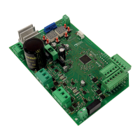
Illustrates primary power, transformer, and battery connections.

Motor and Accessory Wiring Diagrams

Shows electrical connections for motors and system accessories.

Pre-Operation Checks and Settings

Automation System and Motor Configuration

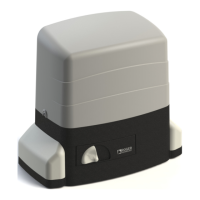
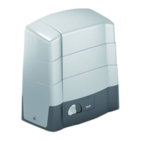
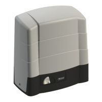
Select automation model (R 1) and motor count (70).

Mechanical Stops and Gate Positioning

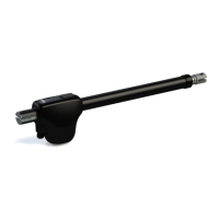
Adjust mechanical stops and move gate to closed position.

Troubleshooting Alarm and Safety Messages

Explains common error codes and safety device messages.

Acquisition Procedure

Automatic Gate Learning Sequence

Step-by-step guide for the automatic gate learning sequence.

Setting Basic Parameters

Position and Deceleration Settings

Details parameters for position control and motor deceleration.

Motor Torque, Speed, and Acceleration

Adjustments for motor torque, opening/closing speeds, and acceleration.

Stop Advance and Alignment Configuration

Parameters for stop advance and motor alignment.

Transmitter and Photocell Management

New Transmitter Programming

Steps to program a new remote control transmitter.

Transmitter Cloning Process

Method for copying an existing transmitter code.

Photocell Grounding for Reliability

Advises connecting photocell COM terminals to system ground for stability.

Related product manuals