EN
10
1
This installaon manual is intended for qualied personnel only.
ROGER TECHNOLOGY cannot be held responsible for any damage or injury due to improper use or any use
other than the intended usage indicated in this manual.
Installaon, electrical connecons and adjustments must be performed by qualied personnel, in accordance
with best pracces and in compliance with applicable regulaons.
Before installing the product, make sure it is in perfect condion
Disconnect the mains electrical power before performing any work. Also disconnect any buer baeries
used.
Only use original spare parts when repairing or replacing products.
The packaging materials (plasc, polystyrene, etc.) should not be discarded in the environment or le within
reach of children, as they are a potenal source of danger.
WARNING
2
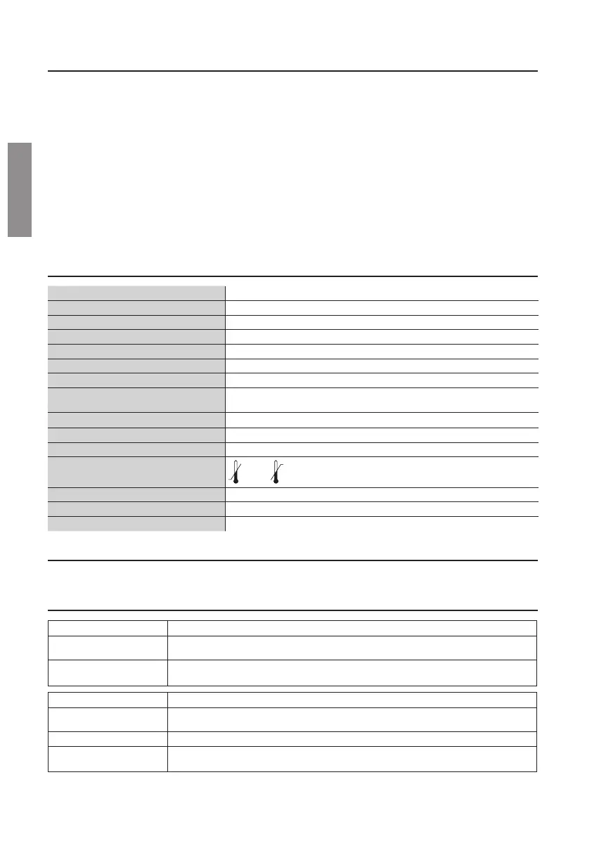
TECHNOLOGY USED Acve infrared, with modulated transmission controlled by a microcontroller
MAINS POWER VOLTAGE 24 Vac/dc
CURRENT ABSORPTION TX= 18 mA, RX= 27 mA
INFRARED BEAM WAVELENGTH 860 nm
LED EMISSION ANGLE ±10°
MAXIMUM OPERATING RANGE 15 m
MINIMUM OPERATING RANGE 0,8 m
OUTPUT CONTACT Double relays with contacts in series (double safety), normally closed contact,
30 V max 0.5 A max with resisve load
SYNCHRONISM digital with wired connecon
RELAY TRIGGER TIME <30 ms
RELAY RELEASE TIME 100 ms
OPERATING TEMPERATURE
-20°C +55°C
DEGREE OF PROTECTION IP55
DIMENSIONS M90/F4ES mm 35x109,8x23,5 - WEIGHT: 100 gr
DIMENSIONS M90/F4ESO mm 45x129,7x40 - WEIGHT: 202 gr
3
The M90/F4S and M90/F4ESO synchronised photocells are infrared obstacle detecon devices.
4
TRANSMITTER TX DESCRIPTION
1(+24V) 2-COM (0V) Power supply 24VAC-DC.
3(SYNC) Synchronism terminal SYNC. Connect the 3-SYNC terminal of the transmier
photocell to the 5-SYNC terminal of the receiver photocell.
RECEIVER RX DESCRIPTION
1(+24V) 2-COM (0V) Power supply 24VAC-DC.
3 /4 (N.C.) N.C. contact. Photocell connecon output.
5(SYNC) Synchronism terminal SYNC. Connect the 5-SYNC terminal of the receiver
photocell to the 3-SYNC terminal of the transmier photocell.
 Loading...