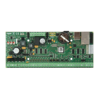
Note: Whenever the low level configuration of the MC16 controller is changed, it is necessary to detect the
controller in VISO software and upload the high level configuration.
MEMORY RESET
Memory Reset procedure erases all low level configuration settings including communication key (none) and
default IP address of the controller (192.168.0.213). In case of firmware 1.3.2 or older the service IP
address remains unchanged and is still kept in IP.INI file on the memory card.
Memory Reset Procedure:
1. Remove power supply.
2. Short CLK and IN4 lines.
3. Restore power supply (all LED will flash) and wait min. 6s.
4. Remove connection between CLK and IN4 lines (LEDs stop flashing, LED2 is ON).
5. Wait (approx. 1.5 min) till moment when LED5+LED6+LED7+LED8 will flash what indicates that memory
has been restored to the defaults.
6. Once, the memory is restored to defaults it is necessary to make low level configuration.
7. In case of controller with firmware 1.4.2 for the first time make low level configuration as in case of
controller with firmware 1.3.2.
FIRMWARE UPGRADE
New firmware can be uploaded to the controller using RogerVDM program and selecting Tools -> Update
firmware or by means of memory card using procedure presented below. Make a backup of low level
configuration and save the settings to file as firmware upgrade usually restores factory default settings and
erases communication key.
Firmware upgrade procedure via memory card:
1. Remove power supply.
2. Remove memory card from the controller.
3. Copy the new firmware to the memory card and rename it as FW.BUF.
4. Insert the memory card back again to the controller socket.
5. Power up the unit and controller will automatically start the firmware upgrade process. During this
process, which usually takes 10s, LED2 is ON while LED3 is flashing.
6. Once the upgrade is finished the FW.BUF file is automatically erased and controller returns to service
mode (LED3 is OFF, LED2 is ON).
7. Run RogerVDM utility program and make low level configuration or restore previous one from backup.
8. Once the configuration is accomplished, restart controller and run VISO program in order to enrol
controller into RACS 5 database.
Note: During the firmware upgrade process, it is necessary to ensure continuous and stable power supply
for the MC16 module. The power supply failure may result in device repair by Roger service.
POWER SUPPLY
MC16 module requires to be supplied from 230VAC/18VAC/40VA transformer. Optionally, it can be supplied
from 12VDC or 24VDC. In case of 12VDC power supply the MC16 does not support backup battery.
 Loading...