EasyManua.ls Logo

Roger PR301 - User Manual

Roger PR301
18 pages
Print Icon
To Next Page IconTo Next Page
Loading...
02-07-29
RACS
Roger Access Control System
Access controller with integrated
reader and keypad
PR301
Version 2.1
Installation and programming manual
Question and Answer IconNeed help?

Do you have a question about the Roger PR301 and is the answer not in the manual?

Overview

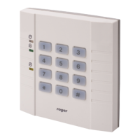
The PR301 is an access controller with an integrated proximity reader and a 12-digit keypad, designed for use in access control systems equipped with electric door locks. It can operate in standalone mode or as part of a networked system controlled by a HOST (PC or CPR control panel). The device supports up to 1000 users, who can be identified by card, PIN-code, or both. An additional identification terminal (reader) can be connected for two-sided door control or when the controller needs to be located in a protected area.

Function Description:

  • Access Control: The primary function is to grant or deny access through a door lock based on user identification.
  • User Identification: Supports card-based, PIN-code based, or dual identification (card and PIN-code) methods.
  • User Types: Distinguishes between several user types:
    • INSTALLER: Authorizes entry to the installer programming mode; has no identification number.
    • MASTER (ID 000): Authorizes entry to user programming mode, door opening, and switching the reader between ON/OFF conditions.
    • SWITCHER Full (ID 001-049): Authorizes door opening and switching the controller between ON/OFF mode.
    • SWITCHER Limited (ID 050-099): Authorizes only switching the controller between ON/OFF conditions.
    • NORMAL (ID 100-999): Authorizes only door opening.
  • Operating Modes:
    • Standalone Mode: The controller operates autonomously, granting access to all programmed users. Event recording, user groups, and time schedules are not available. Programming can be done locally via a MASTER identifier or remotely from a PC.
    • Networked Mode (without CPR): A PC running RACS 2.x software acts as the HOST. This mode enables event recording, access time schedules, remote interactive commands, events monitoring, and different user groups. If the PC stops functioning, controllers automatically revert to standalone mode with frozen access rules.
    • Networked Mode (with CPR): A CPR (Control Panel) acts as the HOST. The PC is used for system configuration and event downloading. Online event monitoring and interactive commands are available if the PC is continuously connected. Events are instantly transferred to the PC database and can be appended to .txt files. If the PC is disconnected, the CPR saves events in an internal buffer.
  • ON/OFF Mode: The controller can be in ON (green) or OFF (red) mode. In OFF mode, the SWITCH output is inactive; in ON mode, it's active. This output is typically for alarm system integration but can be used for other purposes.
    • Control Methods: ON/OFF mode can be controlled locally by SWITCHER or MASTER identifiers, by an external signal on an input declared as [Input control ON/OFF mode], automatically via an ON/OFF mode schedule (in networked systems), or remotely via RACS software.
    • Manual Control: Two consecutive uses of a MASTER or SWITCHER (ID 001-049) identifier, or a single use of a SWITCHER (ID 050-099) identifier, can toggle the ON/OFF mode.
  • Door Opening: The door can be opened by MASTER, SWITCHER Full (ID 001-049), NORMAL identifiers, or by pressing the exit button. The door remains open for the [Time for entry] interval.
  • Alarms: The controller recognizes and signals several alarm conditions:
    • PREALARM (Low Priority): Occurs after three consecutive attempts to enter an unknown identifier within 1 minute.
    • DOOR AJAR (Middle Priority): Occurs if the door remains open for longer than the "Time for door closing" interval.
    • FORCED ENTRY (Highest Priority): Occurs if the door is opened without using the controller.
    • Duress Entry: If a user enters a code differing by one digit (plus or minus one) from their original code, it's interpreted as a duress entry, triggering a [FORCED ENTRY] alarm and sending a [DURESS entry] event to the HOST.
  • Programming Modes:
    • User Programming Mode: Allows adding/deleting NORMAL and SWITCHER identifiers. Accessed by entering the MASTER identifier twice.
    • Installer Programming Mode: Provides detailed setup options for the controller. Accessed from User Programming mode via function [8].

Important Technical Specifications:

  • User Capacity: Up to 1000 users.
  • Inputs: Three inputs, configurable for various functions (e.g., door open sensor, exit button, ON/OFF mode control, reporting input). IN3 is permanently set as a [Reporting input] in networked mode.
  • Outputs: One relay output (SWITCH) and two transistor outputs (ALARM).
  • Current Consumption: Approximately 70 mA (reduced from 120 mA in previous versions).
  • Supply Voltage: 10-15 Vdc.
  • Ambient Temperature: 0-50 °C.
  • Dimensions: 105 x 106 x 31 mm.
  • Weight: Approximately 165 grams.
  • Transponder Module:
    • 64-bit ROM memory, pre-programmed.
    • Amplitude modulation ASK (MANCHESTER coded).
    • Operating frequency: 125 kHz.
    • Transmission speed: 2kB/sec.
  • Communication Bus: Max. length 1200m (twisted pair of wires recommended).
  • PC to UT-2 Distance: Max. 15m.

Usage Features:

  • Optical Signalization (LEDs):
    • ON/OFF LED (Red/Green): Indicates ON (green) or OFF (red) mode.
    • OPEN LED: Lights up when the door is open.
    • SYSTEM LED: Indicates various states like standby for MASTER/SWITCHER/INSTALLER Ident, user/installer programming mode, or EEPROM memory damage.
  • Acoustic Signals: Provides feedback for various operations (e.g., RESTART, O.K. signal, programming errors, identifier reading, memory error).
  • Dual Identification Mode: When activated, users must enter both a code and read a card (sequence doesn't matter).
  • "Access may be granted only in ON mode" Option: If activated, access is denied when the controller is in OFF (red) mode.
  • "Bad card timed lock-out" Option: Blocks card/code reading for 3 minutes after three consecutive attempts to enter an unknown card/code within 1 minute.
  • "Re-programming disabled" Option: Disables entry to Installer programming mode; can only be removed by an EEPROM RESET.
  • Multiply Adding of Users: Allows programming multiple cards consecutively for NORMAL or SWITCHER users.
  • EEPROM RESET: Restores default (manufacturing) settings and deletes all existing data. Requires reprogramming of the MASTER identifier.

Maintenance Features:

  • EEPROM RESET: A crucial maintenance feature to restore the device to its factory default settings in case of memory data damage or to remove the "Re-programming disabled" option. This involves pressing the EEPROM RESET pushbutton until the LED OPEN starts blinking (approx. 6 seconds), releasing it, and then programming a new MASTER identifier.
  • Installation Recommendations:
    • Separate wiring for controller and electric lock power supply.
    • Use 1A power supply units for every 4-8 controllers; avoid large power supplies for the entire system.
    • Power supplies should be battery-equipped.
    • All supply negatives should be connected to ground.
    • Avoid connecting supply positives together.
    • Maximum supply voltage dropout between power supply connectors and any controller should be less than 1.0 Volt.
    • Communication Bus should use twisted pair wires for interference resistance.
    • Shielded cables are recommended only if strong electromagnetic interference exists.
    • Install semiconductor diodes near inductive loads (door strikes, electromagnetic locks) to clamp overvoltage spikes and reduce interference.
    • When mounting on metal surfaces, use non-metal spacers (10-20 mm) between the controller and the surface.
  • Firmware Updates: Version 2.1 includes improvements such as reduced current consumption, new interactive commands from HOST, and new input types ([Input control ON-OFF mode], [Reporting input]).
  • Troubleshooting: Optical and acoustic signals provide diagnostic information for various states and errors, such as EEPROM memory damage or programming errors.

Roger PR301 Specifications

General IconGeneral
BrandRoger
ModelPR301
CategoryIP Access Controllers
LanguageEnglish

Related product manuals