PR_033UK.cdr
+ 12V
GND
POWER
SUPPLY
12Vdc
e.g. PS10/20
Electric
lock
Comm. Bus
ALARM
NC
NO
COM
SN330K
RXE020
I max =200mA
RXE020
MAX 1,5A
4,7k4,7k
4,7k
Controller
SN220K
33k
33k
33k
EEPROM RESET
I max =200mA
7N220K
J4
J3
J2
J1
CLOCK
SUPPLY
Exit button
Door sensor
Arm/Disarm alarm panel(zone) or another equipment control
+12V
Alarm signalization
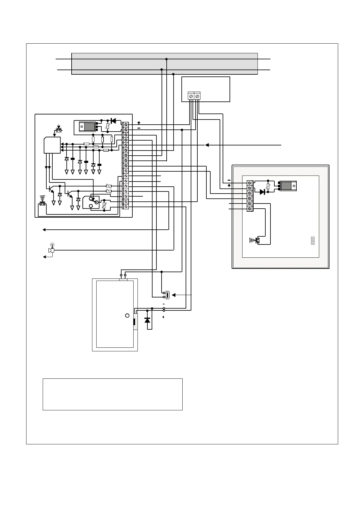
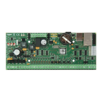
PR301/201 Access Controller
Typical connection diagram of PR301/201 access controller.
Reporting input,
Can be used for any monitoring purpose
IN1
IN2
IN3
SHIELD
B
A
CLOCK
SWITCH
TAMPER
TAMPER
DATA
DATA
Twisted pair of wires recommended.
SHIELD NOTE: use shielded cabels only if strong interferences exists.
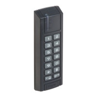
For external location use PRT22 or PRT11.
Electric surge
protection diode
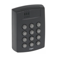
PRTxx Access Terminal ID=0
1. The communication bus length max. 1200m
2. Max. Distance between controller and terminal 300m.
3. The supply voltage reduction between controler (terminal)
and power supply should not exceed 1.0V
4. Electric lock should be supplied using separate wires.
Installation notes