PR301v2.1UK.doc 02-07-29
11
Installation
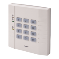
The controller should be hung near the controlled passage, far from any sources of heat and moisture. Electric connections should be
made with the power supply off according to the drawings shown at the end of this manual. After the first time power supply is switched
on, the controller wake in OFF (red) mode with pre-programmed MASTER card and default settings.
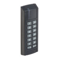
Note: The controller is not fitted for outdoor operation. For outdoor operation the proper additional terminal should be used (e.g. PRT11
or PRT22).
Installation recommendations
1. Supply of the controller and electric lock should be done with separate wires.
2. Use at least one 1A power supply unit for each of 4..8 controllers.
3. Do not use large (above 2A) power supply units to supply access control system, instead of it use many smaller power supply
units located near the powered controllers.
4. Power supplies should be equipped with battery.
5. Connect all supplies minus together to ground potential.
6. Do not connect supplies plus terminal together.
7. The maximum supply voltage dropout between power supply connectors and any controller should be less than 1.0 Volt.
8. It is recommended to lay the Communication Bus with a twisted pair of wires, such a conductor provides a high resistance to
interferences and optimum immunity against disturbances.
9. Install shielded cables only if strong electromagnetic interferences exists, generally shielded cables reduce signal quality.
10. Connect semiconductor diode close to inductive load (door strike or electromagnetic lock), such a diode clamp overvoltages
spikes and reduce interferences generated by access control system.
11. When locating controller on metal surface use additional non metal spacers (about 10..20 mm) between controller and rear
surface.