Getting started
R&S
®
RTM3000
33User Manual 1335.9090.02 ─ 09
[USB] type A (10)
USB 2.0 type A interface to connect a mouse or a keyboard, or a USB flash drive for
storing and reloading instrument settings and measurement data, and to update the
firmware.
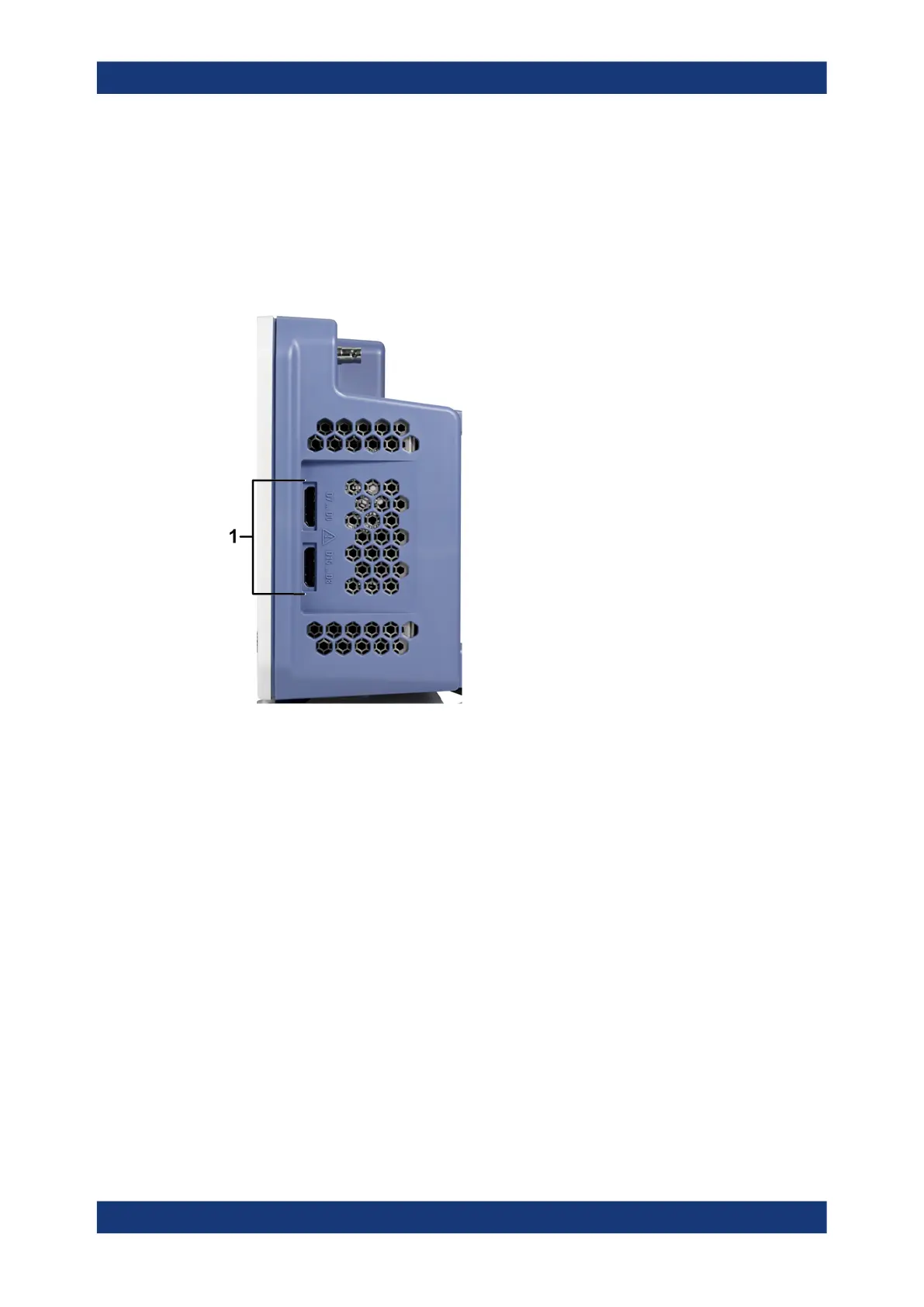
3.2.2 Side view
Figure 3-2: Side view of R&S
RTM3000
1 = Connectors for logic probe (Mixed Signal Option R&S RTM-B1)
Logic probe
The connectors for logic channels can be used if the Mixed Signal Option R&S RTM-
B1 is installed. The option provides connectors for two logical probes with 8 digital
channels each (D0 to D7 and D8 to D15).
The maximum input voltage is 40 V (peak) at 100 kΩ input impedance. The maximum
input frequency for a signal with the minimum input voltage swing and medium hystere-
sis of 800 mV (Vpp) is 400 MHz.
3.2.3 Rear view
Figure 3-3 shows the rear panel of the R&S RTM3000 with its connectors.
Instrument tour
 Loading...


