1976-7-30
SYSTEM
lOO-lOl
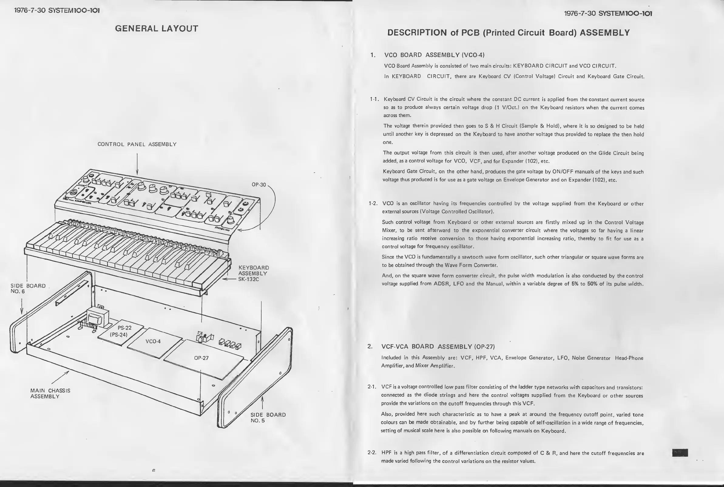
GENERAL
LAYOUT
CONTROL PANEL ASSEMBLY
1976-7-30
SYSTEM100-10I
DESCRIPTION
of
PCB
(Printed Circuit Board)
ASSEMBLY
VCO
BOARD
ASSEMBLY {VCO-4)
VCO
Board
Assembly
is consisted
of
two main circuits:
KEYBOARD
CIRCUIT and
VCO CIRCUIT.
In
KEYBOARD
CIRCUIT,
there are
Keyboard CV
(Control
Voltage) Circuit and Keyboard
Gate Circuit.
-1.
Keyboard CV
Circuit
is
the circuit where the constant DC current
is
applied
from the constant
current source
so
as to
produce always
certain voltage
drop
(1
V/Oct.) on the
Keyboard resistors when
the current comes
across
them.
The voltage
therein
provided
then
goes to
S & H
Circuit
(Sample
& Hold), where it is so
designed
to be held
until another
key is
depressed on the
Keyboard
to
have
another voltage
thus
provided
to replace
the then hold
one.
The output
voltage
from
this circuit is then
used,
after
another
voltage produced
on the Glide
Circuit being
added, as a
control voltage
for VCO,
VCF,
and for
Expander
(102),
etc.
Keyboard
Gate Circuit,
on
the
other
hand, produces the
gate voltage
by ON/OFF manuals
of the
keys and such
voltage thus
produced
Is
for use
as
a
gate
voltage
on
Envelope Generator
and on Expander
(102),
etc.
-2.
VCO is
an
oscillator
having
its
frequencies controlled by
the
voltage supplied from
the
Keyboard or other
external sources
(Voltage
Controlled Oscillator).
Such control
voltage
from Keyboard or other external
sources
are firstly mixed
up in
the Control Voltage
Mixer, to
be
sent
afterward
to
the exponential
converter circuit
where
the voltages so far
having a linear
increasing ratio receive
conversion
to those
having
exponential
increasing
ratio, thereby to
fit for use as
a
control
voltage
for
frequency
oscillator.
Since the VCO
is
fundamentally
a
sawtooth wave form
oscillator,
such
other triangular or
square wave
forms are
to be
obtained through
the Wave Form Converter.
And, on
the
square
wave
form converter circuit, the
pulse width
modulation
is
also conducted
by the control
voltage
supplied, from
ADSR, LFO and
the
Manual,
within a variable
degree of
5%
to 50%
of
its pulse width.
VCF-VCA
BOARD
ASSEMBLY (OP-27)
Included
in
this Assembly
are: VCF, HPF, VCA,
Envelope Generator,
LFO, Noise
Generator Head-Phone
Amplifier, and
Mixer
Amplifier.
1.
VCF
is a
voltage
controlled
low pass filter
consisting
of the
ladder
type
networks
with capacitors
and transistors:
connected as
the diode
strings and here the control
voltages
supplied from
the Keyboard
or other
sources
provide the
variations
on
the cutoff frequencies through
this VCF.
Also,
provided
here
such
characteristic as to have
a
peak at
around
the
frequency
cutoff
point, varied tone
colours can be
made
obtainable,
and by
further
being
capable of
self-oscillation
in
a wide range
of frequencies,
setting of
musical
scale
here
is
also possible
on following
manuals
on
Keyboard.
-2.
HPF
is a
high
pass
filter,
of
a
differentiation circuit composed of
C & R, and here
the
cutoff
frequencies are
made varied
following
the
control variations
on
the resistor
values.



 To Next Page