Tone Parameters
27
LFO1 / LFO2
Parameter
[K] [J] buttons
Value
[-] [+] Buttons
Value
[-] [+] buttons
Waveform
(LFO1, LFO2)
Selects the waveform of the LFO.
SIN Sine wave
TRI Triangle wave
SAW-UP Sawtooth wave
SAW-DW Sawtooth wave (negative polarity)
SQR Square wave
RND Random wave
TRP Trapezoidal wave
S&H
Sample & Hold wave (one time per cycle,
LFO value is changed)
CHS Chaos wave
VSIN
Modified sine wave. The amplitude of a
sine wave is randomly varied once each
cycle.
STEP
A waveform generated by the data
specified by LFO Step 1–64. This produces
stepped change with a fixed pattern
similar to a step modulator.
Rate Sync
(LFO1, LFO2)
OFF
Set this ON if you want the LFO rate to
synchronize with the tempo.
ON
Rate Note
(LFO1, LFO2)
1/64T–4
This is effective if Rate Sync is ON.
Specifies the LFO rate in terms of a note
value.
Rate
(LFO1, LFO2) 0–1023
This is effective if Rate Sync is OFF.
Specifies the LFO rate without regard to
the tempo. Higher values produce a faster
LFO rate (a shorter cycle).
Offset
(LFO1, LFO2) -100–+100
Raises or lowers the LFO waveform
relative to the central value (pitch or
cutoff frequency). Positive (+) value will
move the waveform so that modulation
will occur from the central value upward.
Negative (-) value will move the
waveform so that modulation will occur
from the central value downward.
Rate Detune
(LFO1, LFO2)
0–127
Subtly changes the LFO cycle speed (Rate
parameter) each time you press a key.
Higher values produce wider variation.
This parameter is ignored if Rate is set to
“note value.”
Delay Time
(LFO1, LFO2)
0–1023
Delay Time (LFO Delay Time) specifies
the time elapsed before the LFO effect is
applied (the effect continues) after the
key is pressed (or released).
* After referring to “How to Apply the LFO” (p.
28), change the setting until the desired
effect is achieved.
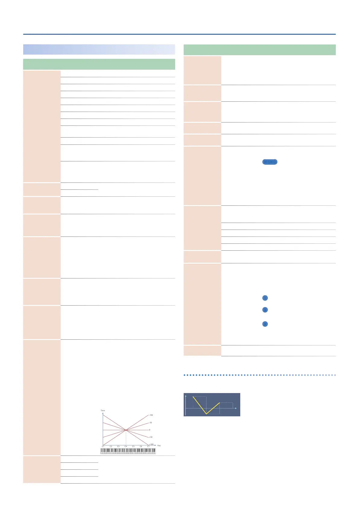
Delay Time
Keyfollow
(LFO1, LFO2)
-100–+100
Adjusts the value for the Delay Time
parameter depending on the key
position, relative to the C4 key (center C).
To decrease the time that elapses before
the LFO effect is applied (the effect is
continuous) with each higher key that is
pressed in the upper registers, select a
positive (+) value; to increase the elapsed
time, select a negative (-) value. Larger
settings will produce greater change. If
you do not want the elapsed time before
the LFO effect is applied (the effect is
continuous) to change according to the
key pressed, set this to “0.”
Fade Mode
(LFO1, LFO2)
ON-IN
Specifies how the LFO will be applied.
* After referring to “How to Apply the LFO”
(p. 28), change the setting until the desired
effect is achieved.
ON-OUT
OFF-IN
OFF-OUT
Parameter
[K] [J] buttons
Value
[-] [+] Buttons
Value
[-] [+] buttons
Fade Time
(LFO1, LFO2)
0–1023
Specifies the time over which the LFO
amplitude will reach the maximum
(minimum).
* After referring to “How to Apply the LFO”
(p. 28), change the setting until the desired
effect is achieved.
Key Trigger
(LFO1, LFO2)
OFF, ON
Specifies whether the LFO cycle will be
synchronized to begin when the key is
pressed (ON) or not (OFF).
Pitch Depth
(LFO1, LFO2)
-100–+100
Specifies how deeply the LFO will affect
pitch.
* If OSC Type is other than VirtualAnalog, the
range is limited to -63–+63.
Filter Depth
(LFO1, LFO2)
-100–+100
Specifies how deeply the LFO will affect
the cutoff frequency.
Amp Depth
(LFO1, LFO2)
-100–+100
Specifies how deeply the LFO will affect
the volume.
Pan Depth
(LFO1, LFO2)
-63–+63
Specifies how deeply the LFO will affect
the pan.
MEMO
Positive (+) and negative (-) value for the Depth
parameter result in differing kinds of change in
pitch and volume. For example, if you set the Depth
parameter to a positive (+) value for one partial, and
set another partial to the same numerical value,
but make it negative (-), the modulation phase for
the two partials will be the reverse of each other.
This allows you to shift back and forth between two
different partials, or combine it with the Pan setting
to cyclically change the location of the sound image.
Phase Position
(LFO1, LFO2)
Specifies the LFO's starting phase value when Key Trigger is
ON.
* This has no effect if Waveform is RND, S&H, or CHS.
0 1 cycle
1 1/4 cycle
2 1/2 cycle
3 3/4 cycle
Step Size
(LFO1, LFO2) 1–16
This is effective if Waveform is STEP.
Specifies the step size that is looped.
Step 1-16
(LFO1, LFO2)
-72–+72
This is effective when Waveform is STEP.
Specify the Depth value of each step.
If you want to specify this in pitch scale
degrees (100 cents), the settings are as
follows.
1
PitchDepth: 51, Step: multiples of
6 … up to one octave of change
2
PitchDepth: 74, Step: multiples of
3 … up to two octaves of change
3
PitchDepth: 89, Step: multiples
of 2 … up to three octaves of
change
* If OSC Type is not VirtualAnalog, the Pitch
Depth setting range is limited to -63–+63, so
only “1” above is possible.
Step Curve 1-16
(LFO1, LFO2)
0–36
Specifies the type of curve at each step.
& “Step curve types” (p. 27)
Step curve types
Step Curve 0
 Loading...