17
Oct. 2010 CUBE-40XL
3. Volume Control Test
When entering Volume Test, all LEDs go off temporarily.
1. Operate the following knobs of (1)–(10) minimum–center–maximum in
numerical order and confirm the all knobs work correctly with its LED
lighting and sound from the speaker.
* If you mistake the order, the knob will not response.
* After detecting all of the minimum, center and the maximum value, test
program advances to test of the next knob.
(1) JC CLEAN VOLUME
(2) EQUALIZER BASS
(3) EQUALIZER MIDDLE
(4) EQUALIZER TREBLE
(5) EFX
(6) DELAY/LOOPER
(7) REVERB
(8) SOLO VOLUME
(9) LEAD VOLUME
(10) LEAD GAIN
The volume level of the speaker sound increases as the control is
operated toward the maximum position, and the pitch rises at the
intermediate position.
When all volume testing has been completed, the LEFT (JC CLEAN),
CENTER, and RIGHT (LEAD) LEDs flash.
This concludes the testing.
Signal-level Test (for Reference)
When components on the circuit board have been replaced, perform this test.
Items Required
• Level meter
• Signal generator
• Dummy load resistor tool
- 8 Ω (100 W or more)
- 1/4-inch stereo phone plug with 100-Ω (1/2 W or more) load resistor
connected between L, R, and GND
Procedure
1. Go to Verifying the Version Number (p. 15) and execute steps 1 through
4.
The version information is displayed.
2. Depress the [SOLO] (red) foot switch connected to the FOOT SW jack.
All LEDs light up, and the unit enters the Level Test mode.
AUX IN to PHONES Output Verification
3. Adjust the LEAD control to ACOUSTIC SIM.
4. To the RECORDING OUT/PHONES jack, connect the 1/4-inch stereo
phone plug 100-Ω load resistors (x 2).
5. Simultaneously input the following signals to AUX IN left and right.
L: 100-Hz, 1-kHz, and 10-kHz sine waves at -20 dBu
R: 100-Hz, 1-kHz, and 10-kHz sine waves at -20 dBu
6. Verify that the output values of the RECORDING OUT/PHONES jack are
as follows.
L: 100 Hz at +1.0±1.5 dBu (flat)
R: 100 Hz at +1.0±1.5 dBu (flat)
L: 1 kHz at -7.0±1.5 dBu (flat)
R: 1 kHz at -7.0±1.5 dBu (flat)
L: 10 kHz at +6.0±1.5 dBu (flat)
R: 10 kHz at +6.0±1.5 dBu (flat)
Speaker Output Verification (1)
3. Adjust the LEAD control to BLACK PANEL.
4. Connect the 8-Ω load resistor to the speaker cables (red and black).
* When detaching the speaker cables, be careful to keep the cable connectors from
being grounded. Failure to do so may damage the Main Board.
5. Input the following signals to the INPUT jack.
100-Hz, 1-kHz, and 10-kHz sine waves at -25.0 dBu
6. Verify that the output values of the speaker are as follows.
100 Hz at +14.0±1.5 dBu (flat)
1 kHz at +14.0±1.5 dBu (flat)
10 kHz at +13.0±1.5 dBu (flat)
Speaker Output Verification (2)
3. Adjust the LEAD control to TWEED.
4. Confirm the 8-Ω load resistor is connected to the speaker cables (red and
black).
5. Input the following signals to the INPUT jack.
100-Hz, 1-kHz, and 10-kHz sine waves at -25.0 dBu
6. Verify that the output values of the speaker are as follows.
100 Hz at +14.0±1.5 dBu (flat)
1 kHz at +14.0±1.5 dBu (flat)
10 kHz at +22.0±1.5 dBu (flat)
Speaker Output Verification (3)
3. Adjust the LEAD control to CLASSIC.
4. Confirm the 8-Ω load resistor is connected to the speaker cables (red and
black).
5. Input the following signals to the INPUT jack.
1-kHz sine wave at -25.0 dBu
6. Verify that the output values of the speaker are as follows.
1 kHz at +14.0±1.5 dBu (flat)
Speaker Output Verification (4) (TUBE LOGIC)
3. Adjust the LEAD control to EXTREME.
4. Confirm the 8-Ω load resistor is connected to the speaker cables (red and
black).
5. Input the following signals to the INPUT jack.
100-Hz, 1-kHz, and 10-kHz sine waves at -35.0 dBu
6. Verify that the output values of the speaker are as follows.
100 Hz at +3.5±1.5 dBu (flat)
1 kHz at +3.5±1.5 dBu (flat)
10 kHz at +1.0±1.5 dBu (flat)
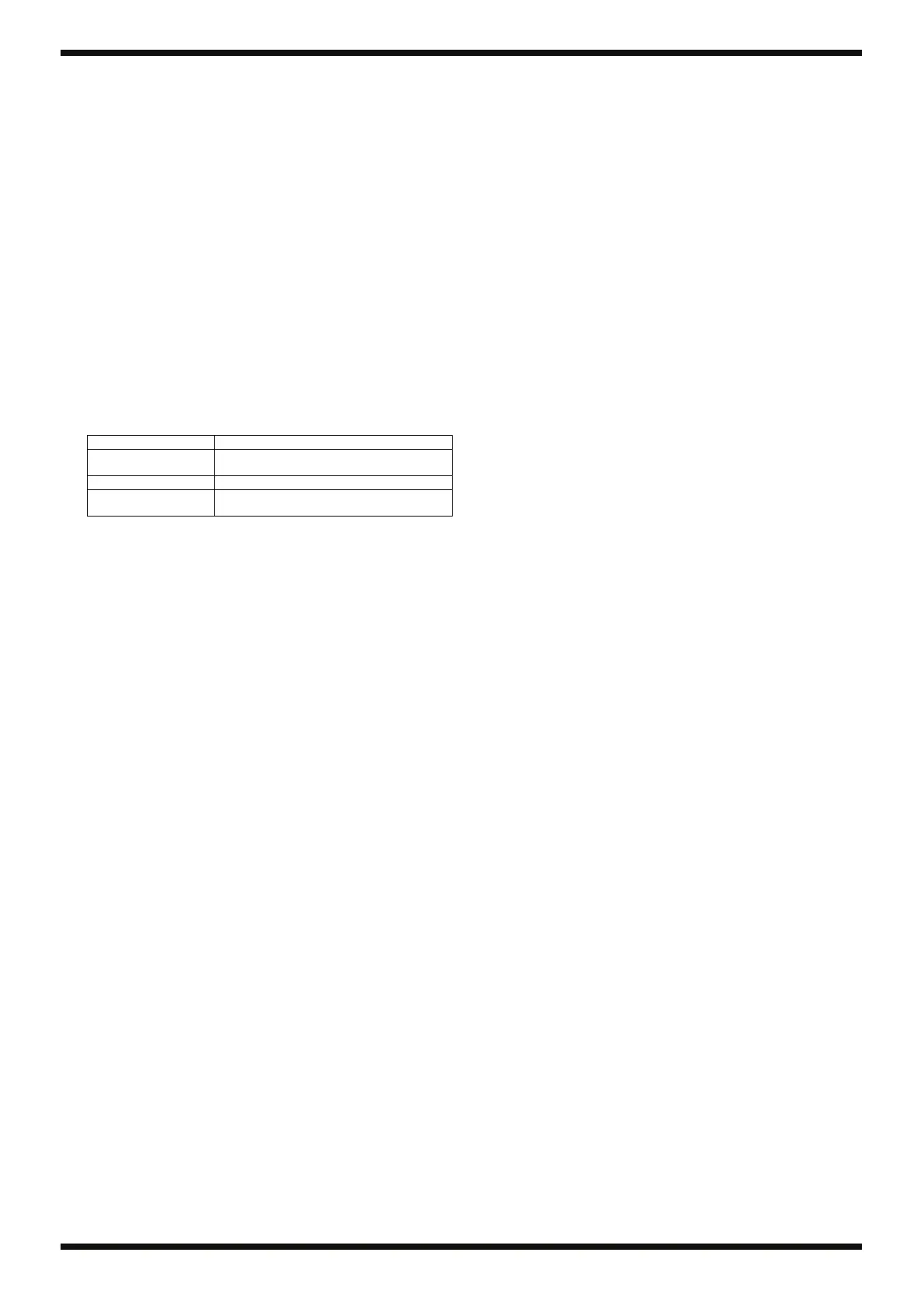
Position of control Lighting LED
Minimum (all the way
counterclockwise)
LEFT (JC CLEAN)
Center LEFT (JC CLEAN), CENTER
Maximum (all the way
clockwise)
LEFT (JC CLEAN), CENTER, RIGHT (LEAD)

 Loading...