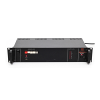
OPERATION
1.
Afler making
the connections, set
the INPUT MODE
switch
®
(rear panel)
as
needed.
Set both the BYPASS
switch
O
and the DIMENSION MODE
@
at OFF.
2. Turn
on the
POWER
switch ©and
check that
the
pilot
light
above
goes
on.
3. Adjust the level of the
external
sound
source so that the
OUTPUT
LEVEL
INDICATOR
©reads close to
• Using levels which
drive
the
LEVEL
INDICATOR ©above
"0"
can cause
distortion. Using
levels which
cause
the
LEVEL
INDICATOR ©to read below
"0"
will
increase the noise level m the
output
signal.
4. Select
MODE©
the desired
DIMENSION
NAMES
AND
FUNCTION OF CONTROLS
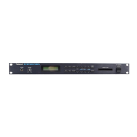
FRONT
PANEL
BYPASS Switch®
The BYPASS
switch® makes direct
connections
between the inputs and
outputs. This means
that the POWER
switch ©may be
left
OFF
when the
SDD-320isin the BYPASS
mode.
© ©
DIMENSION MODE Selectors
@
Selects the dimension mode,
MODE 1
produces the softest effect;
MODE 4
produces the strongest effect. At OFF,
the sound
passes
through the
SDD-320
without
change.
REMOTE Jack®
For remote
switching between the OFF
mode and the DIMENSION
MODE
using
a
foot switch (Roland FS-1
or
DP-
2;
sold separately). To use,
select
a
DIMENSION MODE ©and use
the
foot switch to switch between
the
selected mode and normal
sound.
•
As
an example
of use:
With
an
organ
as
the input sound,
play
a
poigression
of
block chords and use ihe foot switch
so that
some of the chords are
"straight"
and others are "Dimension
D" chords.
If
the Roland DP-2 Pedal
Switch is used, instant changes can
be
made even in very rapid
passages.
The
DIMENSION
MODE IS
in
effect vv-ith [he
DP-2 depressed
and OFF (normal
sound) when
released.
EFFECT INDICATOR©
Lights when the DIMENSION
MODE
is
in effect,
•
Works with both the
REMOTE
jack
©and the
DIMENSION
MODE se-
lectors
® ,
OUTPUT
LEVEL INDICATOR
©
Shows combined
output
level.
(OdB
indication==
+4dBm output),
•
This indicator does
not work when
the
BYPASS
switch
®
is ON (BYPASS
MODE).
POWER Switch
©
with pilot lamp
INPUT MODE Switch
!A)
Selects
the input mode. At
MONO,
left
input is disconnected
and
right
input
serves both dimension
channels.
INPUT Connectors
g
Balanced inputs
(13kfl; max.
+
14dBm).
Pin assignments:
input:
Pin
1
Pin 2
Pin
3
shield (ground)
cold
hot
INPUT
Jacks
C
Unbalanced inputs
(26kn: max,
+
14dBm).
• Do not
use
the balanced and un-
balanced
outputs simultaneously.
OUTPUT
Connectors
(0
Balanced output
{Q(X)U;
nom. level:
-t-4dBm).
Pin assignments same as
INPUT
connectors
©
OUTPUT Jacks
£
Unbalanced
output
(6000;
nom, level:
+ 4dBml.
•
Do not use
balanced and
unbalanced
outputs
simultaneously.
Note: If balanced
inputs are
used,
use balanced
outputs
and vice
versa.
Do
no!
use balanced
out-
puts when using
unbalanced in-
puts, or
unbalanced
outputs when
using
balanced
inputs.
input:
 Loading...