TABLE OF CONTENTS Page
SPECIFICATIONS 1
LOCATION OF CONTROLS EM-20 2
LOCATION OF CONTROLS EM-10 3
EXPLODED VIEW EM-20/EM-10 4
WIRING DIAGRAM EM-20/EM-10 5
KEYBOARD PARTS LIST 5
PARTS LIST EM-20/EM-10 6/7
BLOCK DIAGRAM (EM-20) 8
BLOCK DIAGRAM (EM-10) 9
MAIN PCB ASSY EM-20/EM-10 10
CIRCUIT DIAGRAM MAIN PCB ASSY (EM-20) 11
CIRCUIT DIAGRAM MAIN PCB ASSY (EM-10) 12
CPU PCB ASSY EM-20/EM-10 13
CIRCUIT DIAGRAM CPU PCB ASSY (EM-20) 14
CIRCUIT DIAGRAM CPU PCB ASSY (EM-10) 15
CONTROL PCB ASSY EM-20 16
CIRCUIT DIAGRAM CONTROL PCB ASSY (EM-20) 17
CONTROL PCB ASSY EM-10 18
CIRCUIT DIAGRAM CONTROL PCB ASSY (EM-10) 19
RIGHT CONTACT PCB ASSY w/RUBBER CONTACT & CIRCUIT DIAGRAM 20
LEFT CONTACT PCB ASSY w/RUBBER CONTACT & CIRCUIT DIAGRAM 20
TEST MODE 21/23
Specifications
EM-20/EM-10
1
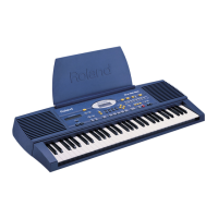
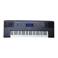
EM-20
GENERAL
61-KEY
TOUCH SENSITIVE KEYBOARD
TOUCH CONTROLLER (Ribbon Controller)
TWO TRACK RECORDER (2nd Track)
BACKLIT CUSTOM DISPLAY
2 x 5 W RMS OUTPUT POWER
8 USER PROGRAM
4 BALANCES
REVERB & CHORUS switches
MELODY INTELLIGENT, LAYER (Upper 1/2)
BASS INVERSION
GENERATION & SOUNDS
24 VOICES POLYPHONY
16 MULTITIMBRAL PARTS
354 TONES AND 12 DRUM KITS
(New Tones - 8 MB PCM Samples)
GM-GS COMPATIBLE
STYLES
64 STYLES ON ROM
STYLE MANIPULATOR (Style Morphing+Style Progression)
MODE
Arranger, Organ, M. Drums
8 ONE TOUCH for each style
CONTROLLERS
PITCH BENDER - MODULATION SWITCHES
DIGITAL VOLUME
CONNECTIONS
REAR POWER SWITCH
JACK OUTPUT (L/mono - R)
SUSTAIN FOOT SWITCH
2 x REAR HEADPHONES
MIDI IN-OUT
POWER SUPPLY 12V 1A ACO Adaptor (230V)
For the other voltages see on page. 7
DIMENSIONS
960 (W) X 380 (D) X 128 (H ) mm
WEIGHT
7.10 Kg
ACCESSORIES
See details on page 7
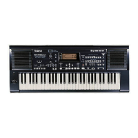
EM-10
GENERAL
61-KEY
TOUCH SENSITIVE KEYBOARD
TWO TRACK RECORDER (2nd Track)
BACKLIT CUSTOM DISPLAY
2 x 3 W RMS OUTPUT POWER
8 USER PROGRAM
2 BALANCES
CHORUS/REVERB switch
MELODY INTELLIGENT
GENERATION & SOUNDS
24 VOICES POLYPHONY
16 MULTITIMBRAL PARTS
226 TONES AND 9 DRUM KITS
(1 MB PCM Samples)
GM-GS COMPATIBLE
STYLES
64 STYLES ON ROM
STYLE MANIPULATOR (Style Morphing+Style Progression)
MODE
Arranger / M. Drums
8 ONE TOUCH for each style
CONTROLLERS
DIGITAL VOLUME
CONNECTIONS
REAR POWER SWITCH
SUSTAIN FOOT SWITCH
REAR HEADPHONES 1/OUT
REAR HEADPHONES 2
MIDI IN-OUT
POWER SUPPLY 12V 500mA ACN Adaptor (230V)
For the other voltages see on page. 7
DIMENSIONS
960 (W) X 380 (D) X 128 (H ) mm
WEIGHT
7.00 Kg
ACCESSORIES
See details on page 7
July, 1999
Issued by RES
SN00029 K6018357 Printed in Italy (AC00) (AD)
Copyright © 1999 by ROLAND CORPORATION
All rights reserved. No parts of this publication may be reproduced in any form whithout the written permission of ROLAND CORPORATION.
SERVICE NOTES
DISASSEMBLY