EasyManua.ls Logo

Roland JUNO-106 Service Manual

Roland JUNO-106
13 pages
To Next Page IconTo Next Page
Page #1 background imageLoading...
Page #1 background image
JUL.
31,
1984
JUNO-106
SPECIFICATIONS
KEYBOARD
61
keys,
5
octaves,
C
scale
Dco
TUNE
+50
cents
LFO
MOD.
+400
cents
BENDER
+1200
cents
VCF
CUTOFF
FREQ.
5Hz
to
50kHz
RESONANCE
0
to
self
oscillation
ENV
MOD.
+14
octaves
LFO
MOD.
+3.5
octaves
BENDER
+3,5
octaves
KEY
FOLLOW
+3/—2
octaves
i=Roland
Side
panel
(left)
(21125190)
Bracket
(22125519)
LED
Display
window
(22245511)
LED
LB-602VA2-1
(15029175)
Bender
panel
(22215722)
SN
435500-up
(22215722A)
PORTAMENTO
ON/OFF
Switch
mounting
hole
----
SQUARE
(Compatible,
see
Parts
Notes)
Bender
ass’y
PB-9
(23275751)
JUNO-106
SERVICE
NOTES
ENV
ATTACK
TIME
DECAY
TIME
SUSTAIN
LEVEL
RELEASE
TIME
LFO
RATE
DELAY
TIME
AUDIO
OUTPUT
DIMENSIONS
WEIGHT
First
Edition
1.5ms
to
3s
1.5ms
to
12s
0
to
100%
1.5ms
to
12s
0.1Hz
to
30Hz
0
to
3s
L:
—30dBm;
M:
—15dBm;
H:
OdBm
992(W)x320(D)x120(H)mm
39-1/16
(W)x12-5/8(D)x
4-11/16(H)
in.
10kg/22
Ib.
POWER
CONSUMPTION
25W
(20W--100V)
Side
panel
(right)
(21125189)
Bracket
(22125519)
Top
panel
(22215408)
Keyboard
SK-361GR
(76139200)
Printed
in
Japan
B-3
1
CPU
board
(76139140)
Power
board
100/117V
(76139121)
220/240V
(76139124)
Panel
board
(76139320)
Jack
board
(76139350)
MIDI
board
(76139380)
Screw
:
Ve
Screw
M3x12
A
:
M3x12
Fe
Br
2
pcs,
;
S
Fe
Br
2
pcs.
Bender
board
{not
shown)
(76139410)
Fuse
board
100/117V
(76139111)
Blind
(22235320)
220/240V
(76139114)
Module
board
(76139170)
Power
transformer
(22455371U0)
Slide
switch
400/117/220/240V
SSP323-12N
(13159334)
Power
switch
WK2A44
3A
(13149108)
or
1801-0121
(14149102)
Jack
(stereo)
HLJO520-01-010
(13449126)
AC
inlet
PA126
(13429710)
117/220V
PA125
(13429709)
240V
DIN
socket
(triple)
MIDI
3-NS
(13429168)
Jacks
(mono)
HLJ0520-01-110
(13449125)
Rubber
foot
G-5
(15mm
or
0,6
in.)
or
G-7
(40mm
or
0.4
in.)
(12359104)
(12359105)
Four
feet
should
be
of
the
size
to
rest
the
unit
level.
Cabinet
(21135130)

Other manuals for Roland JUNO-106

Question and Answer IconNeed help?

Do you have a question about the Roland JUNO-106 and is the answer not in the manual?

Roland JUNO-106 Specifications

General IconGeneral
TypeAnalog
Polyphony6 voices
EffectsChorus
Keyboard61 keys
Memory128 patches
Year Released1984
Oscillators1 DCO per voice
LFO1 LFO
Envelopes1 x ADSR envelope

Summary

Service Notes

Specifications

Technical parameters of the JUNO-106 synthesizer, including key, LFO, VCF, and audio specs.

Component Layout Diagrams

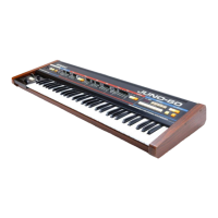
Visual identification of main components and their physical locations on the unit.

Block Diagram

System Signal Flow

Illustrates the interconnection and signal paths between major internal boards.

Module Board

Parts Designation and Pinouts

Lists components on the module board and their pin functions for reference.

Oscillator and D/A Converter Circuits

Details the OSC, DCO, and D/A converter circuitry and timing charts.

Circuit Details

Waveform Generation ICs

Explanation of MC5534A ICs for generating different waveforms.

Integrated Circuit Information

Provides data sheets, block diagrams, and pin configurations for key ICs.

VCF and VCA Circuitry

Description of the Voltage Controlled Filter and Amplifier circuitry.

Board Overviews

Panel Board Diagram

Diagram and explanation of the panel board, including controls and indicators.

CPU Board Diagram

Diagram and explanation of the CPU board, the synthesizer's central control unit.

Parts Designation List

Component Cross-Reference

Lists component designations and their corresponding part numbers for service.

Adjustment Procedures

Power Supply Voltage Checks

Verification of DC supply voltages on the power supply board.

DCO CV Offset Adjustment

Setting the DCO control voltage offset for accurate pitch.

VCA Bias and Offset Adjustments

Fine-tuning VCA bias and offset parameters for proper volume control.

VCF Resonance and Gain Adjustments

Setting VCF resonance and VCA gain levels for sound shaping.

VCF Frequency and Width Adjustments

Tuning VCF frequency and width parameters for tone control.

Noise Level and PWM Adjustments

Setting noise level and pulse width modulation (PWM) for timbre.

Chorus Bias and Load Offset

Adjusting chorus bias and load offset values for audio output.

MIDI Function Switch Check

Verifying functionality of MIDI control switches.

Board Diagrams and Layouts

Module Board Layout

Component layout and wiring for the module board.

Jack Board Layout

Component layout and wiring for the jack board.

Bender Board Layout

Component layout and wiring for the bender board.

Fuse Board Layout

Component layout and wiring for the fuse board.

Power Supply Board Layout

Component layout and wiring for the power supply board.

Related product manuals