15
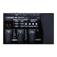
Feb. 2010 ME-25
3. VR Check
Operate the knobs shown in the following chart in the sequence shown under No. and verify the reading of the 7-segment LED display.
fig.test3-1.eps
When all of four knobs have been checked, test program advances to the next item automatically.
4. EXP (Expression Pedal) VR Check and Calibration
1. The 7-segment LED display shows Pd, then UP appears.
fig.test4-1.eps
2. Depress the heel side of the expression pedal all the way and press [WRITE].
The message dn appears on the 7-segment LED display.
fig.test4-2.eps
3. Depress the toe side of the expression pedal all the way and press [WRITE].
The message 5 appears on the 7-segment LED display.
* This 5 is the sensitivity of the expression-pedal switch. It is set to 5 by default.
4. Depress the toe side of the expression pedal more forcefully and verify that the PEDAL FX LED lights up.
5. Again depress the toe side of the expression pedal forcefully and verify that the PEDAL FX LED goes dark.
6. Press [EXIT] to move to the next test.
No. knob knob position and reading on the 7-segment LED display
1 VARIATION
Verify that the 7-segment LED display changes with each click.
2 DRIVE
3 TONE
4 VOLUME
1 234
1 102 9
MIN MAX
MIN MAX
MIN MAX
The Reading Shown on the 7-segment LED Display
When UP is shown, dots are also displayed at the same time.
Left dot: This indicates that calibration was executed when the unit was shipped from the factory.
Right dot: This indicates that calibration has been executed one or more times by the user or a service technician
since the unit was shipped from the factory.
* This calibration record cannot be reset.
The ME-25 records the expression-pedal calibration history. Executing this in the User Mode (Owner’s Manual p. 12)
overwrites the calibration record left by the user.
If the pedal operates in an unexpected way, examining the calibration history may allow determination of a problem
in the factory-default calibration or in calibration performed by the user.
 Loading...