Do you have a question about the Roland ME-25 and is the answer not in the manual?
Notes on power, data backup, parts list conventions, and circuit diagrams.
Step-by-step guide to calibrate the expression pedal and understand its history.
Instructions for entering Test Mode for service purposes.
Details AD/DA conversion, sampling frequency, and AF method.
Specifies memory capacity, sound library categories, and effect types.
Details connectors, input/output levels, and impedance.
Describes the display type and power supply requirements.
Information on current draw, dimensions, and weight of the unit.
Lists standard accessories and available options.
Diagram and list identifying all controls, their numbers, and part codes.
Visual representation of the ME-25's components for service.
Lists main unit parts, PWB assemblies, screws, nuts, and washers.
Guidance on replacing key components, noting part compatibility and modifications.
Lists safety precautions, casing, chassis, switch, and jack components.
Details PWB assemblies, diodes, potentiometers, and cables.
Lists screws, miscellaneous parts, and standard accessories like manuals.
Procedure to check the ME-25's firmware version.
Instructions for data management and performing a factory reset.
Lists items needed and procedure for updating the ME-25's system firmware.
Lists required equipment and steps to enter Test Mode for diagnostics.
Exiting Test Mode, skipping items, and performing version/device checks.
Tests for current consumption, voltage, switches, and LEDs.
Tests control knobs and calibrates the expression pedal, explaining history.
Verifies PHONES and OUTPUT L/R signal integrity, voltage, and disconnect behavior.
Checks A/D conversion, AUX input, clipping, and residual noise levels.
Verifies USB connectivity and battery power functionality.
Illustrates the main functional blocks and signal flow of the ME-25.
Shows MIX, EEP-ROM, USB, and other signal processing components.
Visual layout of components on the main circuit board.
Detailed view of component labels and placement on the main PCB.
Schematic of analog input, power supply, and bias circuits.
Schematic of analog output stages and amplifier ICs.
Schematic showing digital signal paths, USB, ESC, and LED sections.
Schematic of switch section, microcontroller interface, and update logic.
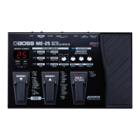
The BOSS ME-25 is a guitar multiple effects processor designed to offer a wide range of sound shaping capabilities for guitarists. It integrates various effects, amp models, and a phrase loop function into a single, user-friendly unit, making it suitable for both practice and performance.
At its core, the ME-25 provides a comprehensive suite of guitar effects, categorized into a "Sound Library" for easy access. This library includes "CLEAN," "CRUNCH," "DRIVE," "HEAVY," "LEAD," and "EXTREME" presets, allowing users to quickly dial in fundamental tones. Within each category, further effect types are available, such as "COMP/FX" (Compressor, T.Wah, AC Sim), "OD/DS" (Boost, OD-1, T-Scream, Blues, Dist, Classic, Modern, Metal, Core, Fuzz), "PREAMP" (Clean, Twin, Tweed, VO Drive, BG Lead, MS Vintage, MS Modern, 5150 Drive, R-Fier, Ultra Metal), "MODULATION" (Chorus, Phaser, Flanger, Rotary, Uni-V, Tremolo, Harmonist, Octave), "DELAY" (various delay times, Tap Tempo), and "REVERB" (Room, Hall). This extensive selection allows guitarists to experiment with and create a vast array of sounds, from subtle enhancements to extreme sonic transformations.
A key feature of the ME-25 is its "COSM AMP MODELING" technology, which emulates the characteristics of various classic and modern guitar amplifiers. This allows users to achieve the tone of different amps without needing to physically own them, providing flexibility for recording and live situations. The "SUPER STACK" function further enhances the amp modeling by simulating the powerful sound of a stacked amplifier setup.
The unit incorporates a "PHRASE LOOP" function, enabling users to record and layer short musical phrases. This is particularly useful for practice, songwriting, and creating dynamic live performances where a backing track or layered guitar parts are desired. The phrase loop can be activated and controlled directly from the unit, offering intuitive operation.
For real-time control over effects, the ME-25 features an expression pedal. This pedal can be assigned to various parameters, such as "PEDAL FX" (Wah, +1 Octave, -1 Octave, Freeze), allowing for dynamic and expressive manipulation of the sound during play. The pedal's sensitivity can be adjusted to suit individual playing styles.
The ME-25 also includes a built-in tuner, accessible via the "TUNER/BYPASS" function, ensuring that the guitar is always in tune. The "MEMORY NUMBER" display, a 7-segment, 2-digit LED, shows the currently selected patch number, while various LEDs indicate the active effects and functions.
Connectivity options include an INPUT jack for the guitar, L/MONO and R OUTPUT jacks for connecting to an amplifier or PA system, a PHONES jack for silent practice, an AUX IN jack for connecting external audio players (e.g., MP3 players) to jam along with, a USB connector for computer connectivity, and a DC IN jack for power. The USB connection allows for data backup/restore and system updates, expanding the unit's capabilities.
The ME-25 is designed for intuitive operation, even with its extensive feature set. The "SOUND LIBRARY" concept simplifies tone selection, allowing users to choose a basic sound type and then fine-tune it with dedicated "DRIVE," "TONE," and "VOLUME" knobs. These knobs, along with the "VARIATION" knob, provide quick access to essential sound parameters. The "PARAM 1," "PARAM 2," and "PARAM 3" controls offer deeper customization for specific effects.
Switching between patches is facilitated by the "MEMORY UP" and "MEMORY DOWN" footswitches, allowing for seamless transitions during live performance. The "SOLO/TAP TEMPO" footswitch serves a dual purpose: activating a solo boost for lead playing and setting the tempo for time-based effects like delay. The "PEDAL FX SW" (switch) integrated into the expression pedal allows users to toggle the assigned pedal effect on or off with a simple press.
The "WRITE" button is used to save customized patches, while the "EXIT" button typically cancels an operation or returns to a previous menu. The "EDIT" button likely provides access to deeper editing parameters for effects and amp models.
Powering the ME-25 is straightforward; it turns on when a plug is inserted into the INPUT jack. This design choice eliminates the need for a separate power switch, streamlining setup. The unit can be powered by either an AC adaptor or six AA-type dry batteries, offering flexibility for different environments.
For computer integration, the ME-25 utilizes a USB connection. This allows users to back up their custom patches and sound library data to a computer, preventing data loss and enabling easy transfer between units or for archival purposes. Similarly, backed-up data can be restored to the ME-25. The USB connection also facilitates system updates, ensuring the unit can benefit from new features or performance enhancements released by the manufacturer.
The ME-25 includes several features and procedures to ensure its proper functioning and longevity.
Data Backup and Restore: User data, including custom patches and sound library settings, can be backed up to a computer via USB. This is a crucial maintenance feature, as it safeguards personalized settings from accidental loss, especially during system updates or factory resets. The process involves connecting the ME-25 to a computer with the appropriate USB driver and MIDI sequencer program, then transmitting SysEx data. Restoring data follows a similar procedure, playing the backed-up SysEx data back to the ME-25.
Factory Reset: A factory reset procedure is available to restore the ME-25 to its original, default settings. This can be useful for troubleshooting issues, clearing all user data, or preparing the unit for a new user. The procedure involves a specific sequence of button presses while powering on the unit, followed by confirmation steps. The ME-25 records the history of factory resets, which can be helpful for service technicians to understand the unit's past usage.
System Updates: The ME-25's system firmware can be updated using a computer and specific MIDI data. This allows the unit to receive new features, bug fixes, or performance improvements. The update process involves connecting the ME-25 to a computer via USB, entering a specific update mode, and then sending the update MIDI data from the computer.
Expression-pedal Calibration: The expression pedal, a critical component for dynamic control, can be calibrated. This ensures accurate response and optimal performance. Calibration involves specific pedal movements and button presses, recording the heel and toe positions. The unit also records the calibration history, which can be valuable for diagnosing issues related to pedal performance.
Test Mode for Service: For service and diagnostic purposes, the ME-25 features a "Test Mode." This mode allows technicians to perform various checks, including:
These test mode functions are invaluable for diagnosing hardware issues, verifying repairs, and ensuring the unit meets its performance specifications. The ability to perform these checks systematically aids in efficient troubleshooting and maintenance.
Parts List and Exploded View: The service notes include an exploded view diagram and a detailed parts list. This information is essential for technicians to identify and order replacement parts, facilitating repairs and component-level maintenance. Important notes are provided regarding parts that have changed specifications over time, ensuring that correct and compatible replacement parts are used.
Overall, the BOSS ME-25 is designed not only as a powerful and versatile guitar effects processor but also with practical considerations for usage and maintenance, making it a robust tool for guitarists.
| AD/DA Conversion | 24-bit |
|---|---|
| Sampling Frequency | 44.1 kHz |
| USB | Yes |
| Display | LCD |
| Type | Guitar Multi-Effects Processor |
| Effects | Overdrive, Distortion, Fuzz, Modulation, Delay, Reverb |
| Patches | 30 User, 30 Preset |
| Looper | 38 seconds |
| Inputs | Guitar Input (1/4" phone type), AUX IN jack (Stereo miniature phone type) |
| Outputs | 2 x 1/4" (L/Mono, R) |
| Expression Pedal | Built-in |
| Power Supply | AC Adaptor (included) |