16
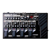
Jan. 2014 ME-80
1. Version Check and Device Check
1. When entering the Test Mode, the device check begins automatically.
* When no USB cable is connected, an error is displayed.
The version appears on the 7-segment LED display and verify that the
triangular LED on the left is lighted.
fig.test1.eps
If the device check results in an error, the location of the error is shown
on the 7-segment LED display.
2. Disconnect the USB cable.
When correct detection occurs, execution automatically advances to the
next test item.
* If an error occurs, execution does not advance to the next test item.
2. Current-consumption Check, Voltage
Detection Check and SW/LED Check
1. Verify that all LEDs are lighted.
Verify that the voltage of the stabilized power supply is 9 V.
2. Measure the current consumption and verify that it is between 140 and
170 mA.
3. Set the voltage of the stabilized power supply to 6.5 V.
Verify that bt appears on the 7-segment LED display.
fig.test2-1.eps
4. Set the voltage of the stabilized power supply to 7.5 V.
Verify that the all LEDs light up.
5. Set the voltage of the stabilized power supply to 9.0 V.
6. Press the switches shown in the following chart in the sequence shown
under No.
When you press each switch, verify that the corresponding LED in the
chart goes dark.
Verify that a clicking sensation is felt when each switch is pressed.
7-segment LED darkening sequence
fig.test2-2.eps
After all have gone dark, press WRITE to advance to the next test item.
Display Location of Error
fig.error1.eps
Serial flash error
fig.error2.eps
App Check Sum error
fig.error3.eps
Updater Check Sum error
fig.error4.eps
USB error
fig.error5.eps
DSP iram0 error
fig.error6.eps
DSP iram1 error
fig.error7.eps
DSP pram0 error
fig.error8.eps
Internal ERAM error
fig.error9.eps
External ERAM error
fig.error10.eps
External ERAM error
fig.error11.eps
UDL Clock error
ig.error12.eps
MONO Test Failed
ffig.error13.eps
A1 Waveform Test Failed
fig.error14.eps
A1 MUTE Test Failed
fig.error15.eps
A1 NOISE Test Failed
fig.error16.eps
A2 Waveform Test Failed
fig.error17.eps
A2 MUTE Test Failed
ig.error18.eps
A2 NOISE Test Failed
ffig.error19.eps
A3 Waveform Test Failed
fig.error20.eps
A3 MUTE Test Failed
fig.error21.eps
A3 NOISE Test Failed
fig.error22.eps
A4 Waveform Test Failed
fig.error23.eps
A4 MUTE Test Failed
fig.error24.eps
A4 NOISE Test Failed
No. Operated switch Darkened LED
1 PEDAL 4 (DELAY) DELAY (Pedal)
2 PEDAL 3 (MOD) MOD (Pedal)
3 PEDAL 2 (OD/DS) OD/DS (Pedal)
4 PEDAL 1 (COMP) COMP (Pedal)
5
BANK PEDAL BANK
6
BANK PEDAL BANK
7 CTL PEDAL CTL
8 MEMORY/MANUAL PEDAL MANUAL
9 MEMORY/MANUAL PEDAL MEMORY
10 EDIT COMP/FX1
11 EDIT OD/DS
12 EDIT MOD
13 EDIT DELAY
14 EDIT PREAMP
15 EDIT EQ/FX2
16 EDIT REVERB
17 EDIT PEDAL FX
18 CTL 7-segment LED 1
19 CTL 7-segment LED 2
20 EXIT 7-segment LED 3
21 EXIT 7-segment LED 4
22 EXIT 7-segment LED 5
23 EXIT 7-segment LED 6
24 EXIT 7-segment LED 7
25 EXIT 7-segment LED 8
26 EXIT 7-segment LED 9
27 EXIT 7-segment LED 10
28 EXIT 7-segment LED 11
29 EXIT 7-segment LED 12
30 EXIT 7-segment LED 13
31 EXIT 7-segment LED 14
32 EXIT 7-segment LED 15
33 EXIT 7-segment LED 16
34 EXIT 7-segment LED 17
35 EXIT 7-segment LED 18
2 1
8 4 16 12
7 5 15
6 14
113
9 17
10 18
13
 Loading...