5.
Switch
and
LED
Check
All LEDs
turn
on.
Press
the
buttons one
by
one
and the
corresponding
LED
will
turn
off
associated
with a
piano
tone.
For
checking
the
7-SEG
LED, press
INC
and
the
upper
segments
will
turn off;
next,
press
DEC and
the
lower
segments
turn off.
Simultaneous
pressing
of
INC
and
TRANSPOSE
goes
to
the
next
test.
6.
A/D
Check
(a)
Slider
Check
Move
LOWER
slider
from
minimum
to
maximum
position.
The
7-SEG
LED
will
show the
name
of the
slider
being
operated,
as
shown in Fig.
6. The
number
of
lighting
LEDs
of the
11
LEDs
shown in
Fig.
5
will
increase
as
the
slider
travels.
When the
maximum
level is
reached a
vibraphone
tone
sounds.
Repeat
the step
for
the
UPPER
and
VALUE
sliders.
5.
X
T
-y
•
LEDf-
i
'7
^
-to
t
^
L
7yLED#M:tTt-
^ 1
iz hi
ry
$
ti
tto
^y'y
y hLEDii.
m
I
.
DEC
INC
t
TRANSPOSE
^
|W]
0^
^
^
Ltto
6.
A/D'T'
J-
'7
y
(a)
yy
4
LOWER,
UPPER,
VAL\]E(D^ysy y
h
g]
5
L
/; 1
1®
tCiS C
T
)I|I#
*
ULtto
\ykyy
tyco^i)^
hEEDK^TE^tltt
Fig.5/05
lower
upper
value
Fig.6/06
(b)
Pedal
Check
(b)
^
y
Operate
the
pedal
connected
to
INT+TX
socket.
The
INT
+
TXi3
J:
ZfTX(D y y
"y
y
^zWB t
LEDs
shown
in Fig.
5
indicate
the
level and the
7-SEG
ikk
^
{a)h
LED
shows
the
name
of the
pedal as
shown
in Fig.7.
1
-Ek
yy
hLEDl'-^/E^
tL^
Thd
vibraphone
tone
will
be
heard as
the
maximum
t
(II17#M)o.
level
is
reached.
Repeat
the step
for the
pedal
connected
to TX
socket.
INT-TX
TX
Fig.7/I2]7
hA^rii ilr>ti/-.n r'hool/' ^ 'V u 'V ^ > -T-
JE,
'7
"7
yoy
iviV-/\-iuiciiivyi
I \-/i iv^v/rv
V'^/
—
-
-
^
Push in
the
bender
lever
and the
similar
sequence
L/s'--
(a)<h
described
in step (a)
above
will take
place.
For the
7-
ti'iko
t
^
7
k
y
y
bLED(/)^7Eti>
0
8
(D
SEG
LED
indication, see
Fig.
8.
X
^
\Zk
^
o
Fig.8/08
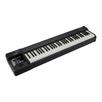
RD-500
Feb,
1994
(d)
Bender Check
Press the bender
lever
to
the left
(right)
and the
left
half (right half) LEDs
shown in
Fig. 9
turn on one
by
one
as
the lever travels. Also check the lighting status
of the 7-SEG
LED
by
referring to Fig. 10.
(d)
^y
y'—k
j:-
y
y
^y
^z$j]:7)^i-
1
,
09
0
7
XzVy
y
LLED0^^i±01O0
<L
^
\zf^^
ko
ol.
n
Fig.1 0/010
This completes the A/D check. Press INC to proceed
to the
next
test.
7.
MIDI Check
The initial state of the 7-SEG LED is as shown in Fig. 11
followed
by the state
shown
in
Fig.1 2.
Hook
up
MIDI IN
and
MIDI
OUT sockets via a
MIDI
cable
and
the 7-SEG
LED changes state as shown in Fig. 13.
Press INC
to proceed to
the next
test.
ik±y:A/Dk^'yy^i'ikiy^y:"to
'^WiiLtko
7.
MIDIf-
X
'7
^
7
xzky
y
hLED
0
^^^^'
0
ii
0 i
d >k
Kmi2<DX
9
^ZMt)
i
i'CMIDI
IN
<L
MIDI
OUT
0y^T^MIDI^-70Ve;L“7°1“^ 0130
ct
7
iNC^ffi"i:^ >kK^^rLtto
Fig.
11/011
Fig.
12/012
Fig.
13/013
8.
Sound Check
8.
Press
a
button shown in Fig. 14 and the corresponding
0I40#4^'7
ykWkt^ ^
tone will sound. Repeat for the remaining
buttons.
9
^
i~o
Fig.
14/014
Button Tone
LOWER
->
PLANO
UPPER
->
VIBRAPHONE
SYNTH
->
ORGAN
STRINGS
->
STRINGS
BASS
->
Chorusing E. PIANO
PERCUSSION
->
Reverberating VIBRAPHONE
Press INC to proceed to the next test.
t7yi>
LOWER
->
PLA^NO
UPPER
->
VIBRAPHONE
SYNTH
->
ORGAN
STRINGS
->
STRINGS
BASS
->y~y
y<Diyiy'^
/iE.PlANO
PERCUSSION
->
VIBRAPHONE
10
HV
r
^
 Loading...