32
The VR-6HD support two types of remote-interface communication: LAN and RS-232.
Using the LAN CONTROL port or RS-232 connector to send specic commands to the VR-6HD from a controlling device lets you operate the VR-6HD remotely.
LAN Interface
This uses the LAN CONTROL port on the VR-6HD.
You use Telnet to operate the VR-6HD remotely over a LAN (TCP/IP
protocol).
Communication standards
Port LAN CONTROL jack
TCP port number 8023
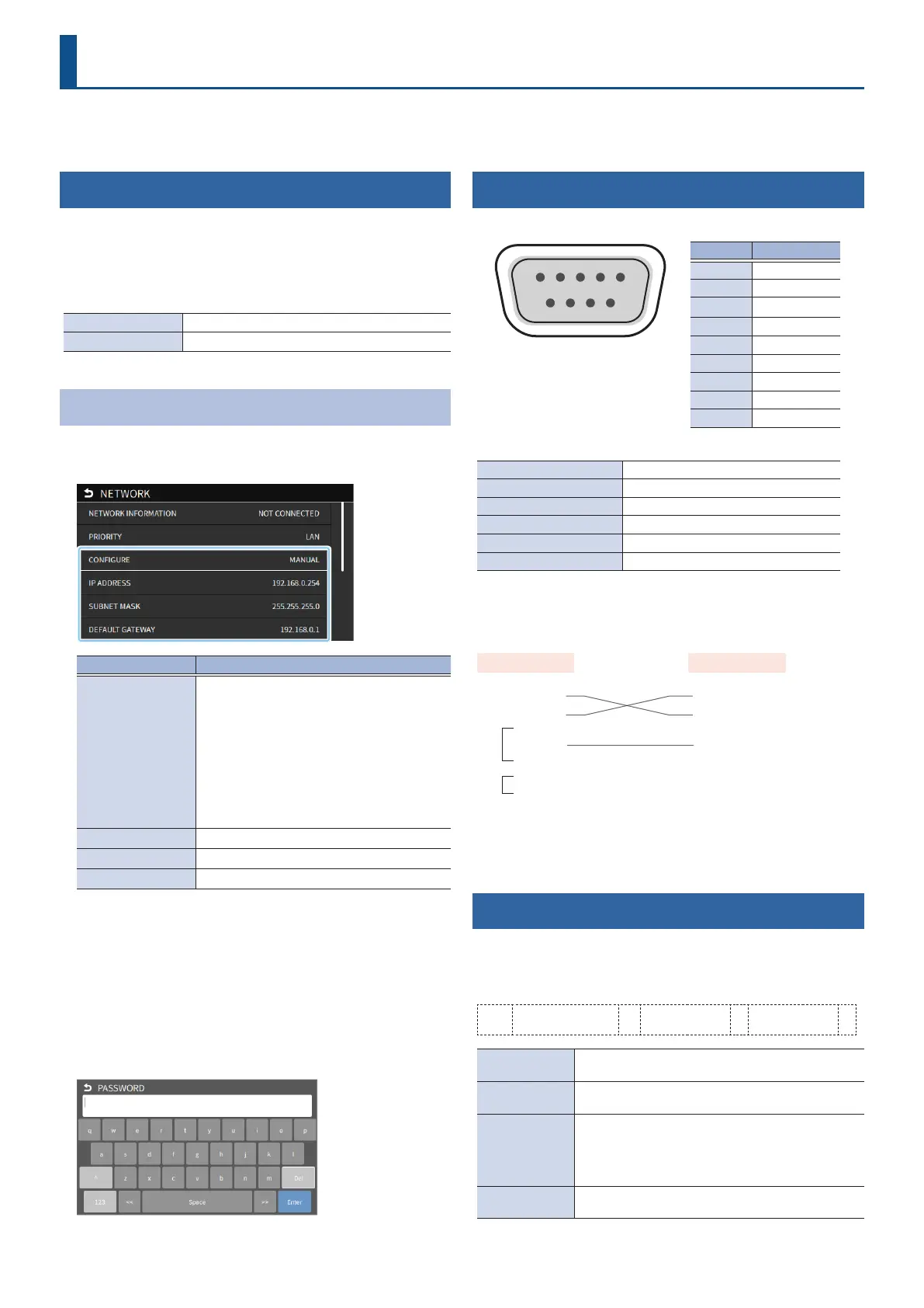
Specifying the VR-6HD’s Network Settings
1. [MENU] button Ó “NETWORK” Ó select the menu item
shown below, and press the [VALUE] knob.
Menu item Explanation
CONFIGURE
Selects how settings are made for the IP
address, subnet mask, and default gateway.
USING DHCP:
The IP address and other information needed
for connecting to the network is obtained
automatically from the DHCP server of the LAN.
MANUALLY:
The IP address, subnet mask, and default
gateway are specied manually.
IP ADDRESS
Shows the IP address. (*1)
SUBNET MASK
Shows the subnet mask. (*1)
DEFAULT GATEWAY
Shows the default gateway. (*1)
(*1) When “CONFIGURE” is set to “MANUALLY”, set these respectively
according to the network.
2. Use the [VALUE] knob to change the value of the setting.
3. Use the [VALUE] knob to select “NETWORK PASSWORD”,
and press the [VALUE] knob.
4. Set a network password (four characters).
Input the password that’s set here when connecting a computer or other
device on the same network to access the VR-6HD.
5. Press the [MENU] button to close the menu.
RS-232 Interface
RS-232 connector pin layout Pin assignments
1 2 3 4 5
6 7 8 9
DB-9 type (male)
Pin No. Signal
1 N.C.
2 RXD
3 TXD
4 DTR
5 GND
6 DSR
7 RTS
8 CTS
9 N.C.
Communication standards
Communication method Synchronous (asynchronous), full-duplex
Communication speed 9,600/38,400/115,200 bps
Parity none
Data length 8 bits
Stop bit 1 bit
Code set ASCII
Cable wiring diagram
Use an RS-232 crossover cable to connect the VR-6HD and the
controller (an RS-232-compatible computer or other device).
VR-6HD Control device
N.C.: 1 1:
RXD: 2 2: RXD
TXD: 3 3: TXD
DTR: 4 4:
GND: 5 5: GND
DSR: 6 6:
RTS: 7 7:
CTS: 8 8:
N.C.: 9 9:
(Crossover connection)
* The connections between 4 and 6 and between 7 and 8 are inside the
VR-6HD.
Command Format
Commands are formatted using the conguration shown below.
Commands are all in ASCII code.
* Commands are common to the LAN and the RS-232 interface.
stx Command code : Parameter , Parameter ;
stx
ASCII code “02H” is a control code indicating the start of
a command. “H” indicates that it is a hexadecimal value.
Command code
This species the command type (three single-byte
alphanumeric characters).
Parameter
This is appended to a command that requires one or
more parameter. The command and the parameter
portion are separated by a “ : ” (colon). When there are
multiple parameters, they are each separated by “ , ”
(comma) characters.
;
This is the code that this unit recognizes as the end of
a command.
* The codes of stx (02H), ack (06H), xon (11H), and xo (13H) are the control
codes.
LAN/RS-232 Command Reference

 Loading...