Basic Safety Instructions
Warning! Read before commissioning!
Read and comply with all these instructions before operating the unit. Save these sa-
fety instructions.
Only use the unit for the purpose for which it was intended, with due attention to the
general safety and accident prevention regulations.
•
Keep work area clean
Cluttered areas invite injuries.
•
Consider work area environment
Keep work area well lit.
•
Keep children away
Do not let contact unit lead. All bystanders should be kept away from work area.
Only allow trained personnel to use it. Apprentices may only operate the machine
when they are older than 16, when this is necessary for their training, and under
the supervision of a trained operative.
•
Dress properly
Do not wear loose clothing or jewellery. They can be caught in moving parts. Rub-
ber gloves and non-skid footwear are recommended when working outdoors. We-
ar protective hair covering to contain long hair.
Use personal safety equipment
Wear safety goggles. Wear safety glasses. Wear ear defenders to protect against
noise
85 dB(A). Wear a face mask if work is dusty.
•
Keep hands away from moving (rotating) parts.
•
Secure workpiece
Use clamps or a vice to hold workpiece. It's safer than using your hand and it fre-
es both hands to operate the unit.
•
Don't overreach
Keep proper footing and balance at all times.
•
Maintain units with care
Keep tools sharp and clean for better and safer performance. Follow instructions
for servicing and changing tools. Inspect unit leads periodically and, if damaged,
have them repaired by an authorised service facility. Inspect extension leads peri-
odically and replace them if damaged. Keep handles dry, clean and free from oil
and grease.
•
Stay alert
Watch what you are doing. Use common sense. Do not operate unit when you are
tired.
•
Check unit for damaged parts
Before further use of the unit, a guard or other part that is damaged should be ca-
refully checked to determine that it will operate properly and perform its intended
function. Check for alignment of moving parts, binding of moving parts, breakage
of parts, mounting, and any other condition that may affect the power tool's opera-
tion. A guard or other part that is damaged should be properly repaired or replaced
by an authorised service facility unless otherwise indicated in the operating in-
structions.
•
Warning
Only use genuine spare parts and accessories, for personal safety reasons, to en-
sure correct operation of the machine. The use of other accessories or attachments
involves a risk of injury.
Specific Safety Instructions
•
Carbon dioxide must be drawn from the cylinder in a liquid state in order to produ-
ce dry ice. For this reason only cylinders which are equipped with a dip tube may
be used. Do not attach a pressure regulator to the cylinder. Keep the cylinder in a
secure upright position.
•
Due to technical reasons, the carbon dioxide cylinder can never be fully emptied.
By no means, do not manipulate nozzles, collars or valves, including cylinder val-
ves.
•
Always ensure that there is sufficient ventilation, particularly in confined spaces.
Carbon dioxide is non-toxic and non-flammable, however it is heavier than air and
can therefore collect, for instance in submerged work pits, and displace oxygen.
Thus risk of suffocation!
•
Wear eye protectors, e.g. safety glasses.
•
Always wear gloves.
•
Welding or soldering work should not be performed within approx. 60 cm of the fre-
ezing point.
•
Do not hit with tools against freezed collars (risk of fracture).
•
Keep all other persons, particularly children, as well as animals away. Dry ice cau-
ses burns if it comes into contact with the skin. Once work is complete, any remai-
ning dry ice in the freeze collars must be carefully disposed of, e.g. placed in a co-
vered refuse container such as a dustbin.
•
Ensure compliance with safety regulations of the carbon dioxide manufacturers.
1. Technical Data
1.1. Working range
Liquids of all types such as water, milk, beer etc. in pipes made from steel,
copper, cast iron, lead, aluminium, plastic etc. Pipe sizes
1
/
8–2 respectively
10–60 mm.
The ice pack which forms in the pipe is capable of withstanding a pressure of ap-
prox. 500 bar.
1.2. Refrigerant
Carbon dioxide (CO
2
), commercially available in cylinders of various sizes. It is
recommended that users purchase the largest cylinder size possible.
1.3. Noise data
Emission at workplace 75 dB (A).
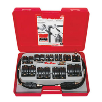
2. Preparations for Use
Remove the seal from the carbon dioxide cylinder. Screw connector with T-distributor
to cylinder valve (right-hand thread). Screw high-pressure hoses to the T-distributor.
Screw on the handle piece with injector nozzle to the high-pressure hoses (Fig. 1).
Choose freeze collars which correspond to the size of the pipe to be frozen. Place the
freeze collars on the pipe and secure by tightening the screws evenly to give a firm but
not overtight hold (Fig. 2). Turn and, at the same time, push each handle piece with in-
jector nozzle into the bore of the freeze collar until it is completely inserted and resting
against the stop (Fig. 3).
If one only operates with one collar, the free side of the T-distributor has to be closed
by the closing nut. If a 3. or further freezing points are required, additional T-distribu-
tors (accessory) can be connected to the T-distributor.
3. Operation
The water (or other liquid) in the pipe can only be frozen when it is no longer flowing.
All pumps must therefore be stopped and no liquid removed or allowed to escape from
the pipe. Before freezing, let the water cool down to room temperature.
Fully open the cylinder valve. The amount of carbon dioxide required is controlled au-
tomatically. The liquid carbon dioxide expands in the injector and forms dry ice with a
temperature of –79°C and freezes the water within the pipe. After a brief period, frost
will form on the pipe in the vicinity of the freeze collars. If frost does not form in accor-
dance with time given in the table, then this indicates that the liquid within the pipe is
still flowing (check that all pumps have been switched off and prevent any removal or
outflow of water) or the water is too warm. While work is in progress, the flow of carb-
on dioxide refrigerant must be maintained. Always ensure a sufficient supply of refri-
gerant by providing a stand-by cylinder.
The only way to determine the amount of remaining carbon dioxide is to weigh the cy-
linder.
If it is necessary to change the cylinder during work, it is essential that this procedure
should be complete within 7 minutes to prevent the ice pack from melting.
Once work is complete, close the cylinder valve and wait until the pressure in the high-
pressure hoses has returned to normal. Remove the high-pressure hoses. Once the
ice pack has completely melted, carefully unscrew and remove the handle pieces
with injector from the freeze collar and remove the freeze collar.
4. Freezing Times
The freezing times and carbon dioxide requirements given in the table below are only
to be regarded as general guidelines and are valid for a water temperature of approx.
20°C. The freezing times and refrigerant consumption values will therefore vary for hig-
her temperatures. For freezing liquids in plastic pipes much longer freezing times are
generally required.
Table:
* Does not include work time
5. Procedure in Case of Trouble
Fault:
Frost does not form on the pipe.
Cause:
•
Freezing time still too short. Pay attention to freezing times
according table.
•
Pumps not switched off, outflow of water.
•
Carbon dioxide cylinder is empty or cylinder valve is not open.
•
Choke in cylinder connector with T-distributor is blocked up.
•
Filter in front of injector nozzle blocked up. Unscrew injector nozzle,
push filter carefully from the back through the handle piece, clean
filter (blow out).
6. Guarantee Conditions see last page.
GB GB
Freeze collar Material Freezing Carbon dioxide Number of freezing
size time consumption operations possible
per freeze collar
per 10 kg cylinder*
1
/8/10/12 mm steel 1 min 60 g 165
copper 1 min 65 g 160
1
/4/ 15 mm steel 1 min 75 g 130
copper 2 min 135 g 75
3
/
8
/ 18 mm steel 2 min 150 g 65
copper 3 min 200 g 50
1
/
2
/ 22 mm steel 3 min 225 g 45
copper 5 min 330 g 30
3
/4/ 28 mm steel 5 min 350 g 29
copper 7 min 450 g 22
1 / 35 mm steel 7 min 500 g 20
copper 10 min 650 g 15
1
1
/4/ 42 mm steel 11 min 700 g 15
copper 14 min 900 g 11
1
1
/2 steel 16 min 1050 g 10
54 mm copper 24 min 1450 g 7
2 / 60 mm steel 29 min 1900 g 5
 Loading...