Air
Conditioning
System
Manual
-------
Rolls-Royce
&
Bentley-------------
·--~------
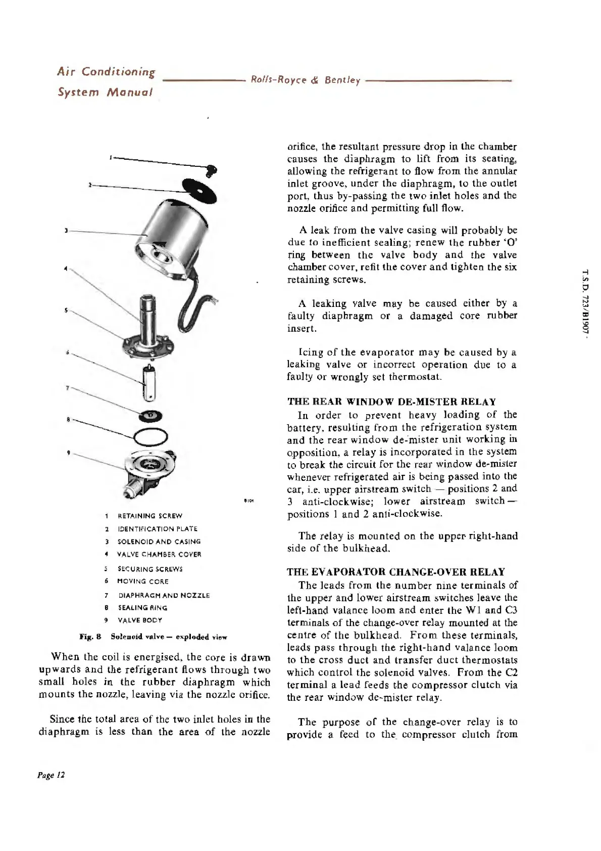
1
RE
TAINING
SCREW
2 I
DENTIFICATION
PLATE
3 SOLENOID
AND
CASING
4 VALVE CHAMBER COVER
5 SECURING SCREWS
6
MO
V
ING
CORE
7 DIAPHRAGM
AND
NOZZLE
B SEALING
RING
9 VALVE
BODY
Fig.
8 So!P.nold
valve
-
exploded
view
When
the coil is energised,
the
core
is
drawn
upwards
and
the
refrigerant
flows
through
two
small
holes
in
the
rubber
diaphragm
which
mounts
the
nozzle, leaving via the nozzle orifice.
Since the total area
of
the two inlet holes in the
diaphragm
is less
than
the
area
of
the nozzle
Page 12
orifice, the resultant pressure
drop
in the chamber
causes
the
diaphragm
to
lift
from
its seating,
allowing the refrigerant to flow
from
the annular
inlet groove,
under
the
diaphragm,
to
the
outlet
port, thus by-passing the two inlet holes
and
the
nozzle orifice and permitting full flow.
A leak
from
the
valve casing will
probably
be
due
to
inefficient sealing;
renew
the
rubber
'O'
ring between
the
valve
body
and
the valve
chamber cover, refit
the
cover
and
tighten
the
six
retaining screws.
A leaking valve may be caused either by a
faulty
diaphragm
or
a
damaged
core rubber
insert.
Icing
of
the
evaporator
may
be
caused
by a
leaking valve
or
incorrect
operation
due to a
faulty
or
wrongly set thermostat.
THE REAR WINDOW DE-MISTER RELAY
In
order
to
prevent
heavy
loading
of
the
battery,
resulting
from
the
refrigeration
system
and
the
rear
window
de-·
mister
unit
working in
opposition, a relay is
incorporated
in the system
to break the circuit for the rear window
de
-mister
whenever refrigerated air is being passed into the
car, i
.e
.
upper
airstream switch - positions 2 and
3 anti-clockwise; lower
airstrcam
switch -
positions 1
and
2 anti-clockwise.
The relay
is
mo
unted
on the uppeI' right-hand
side
of
the
bulkhead
.
THE EVAPORATOR CHANGE-OVER RELAY
The
leads
from
the
number
nine
terminals
of
the
upper
and
lower
airstream
switches leave the
left-hand valance
loom
and
enter
the
WI
and
C3
terminals
of
the change-over relay mounted at the
centre
of
the
bulkhead
.
Fro
m these terminals,
leads
pass
through
the
right-hand
valance
loom
to
the
cross
duct
and
transfer
duct
thermostat
s
which
control
the so
len
o
id
valves.
From
the
C2
terminal a
lead
feeds
the
compressor
clutch
via
the rear window de-mister relay.
The
purpose
of
the change-over relay is to
provide a feed
to
the. compressor clutch from
"'
0
....