-------------
Rolls-Royce
&
Bentley
-------
Air
Conditioning
System
Manual
••
Fig.
9
Blower
motor
-
exploded
vie>o"
either
of
the
independently operated airstream
switches.
The
C3
and
C2
contacts
are
norm
ally closed,
allowing a feed
when
the
lower
switch
is
turned
to
an
anti-clockwise
position
.
Operation
of
the
upper switch to
a 'cool' po~ition energises the
winding
and
'makes'
the
Cl
and
C_2 contacts.
THE BLOWER MOTORS
Model . .
Smiths
FHM
5342/
01
Two identical
motor
s are utilised in the system:
the fresh
air
blower s
ituated
in
the
inl
et
ducting
beneath the wing,
and
the recirculation blower
mounted in the recirculation inlet duct beneath
the front
flo
or, to
th
e r
ea
r
of
the lower evaporator.
Each
motor
and fan
is
mounted
in a cast
aluminium housing (see Fig.
9)
.
The
motor
shaft
is
carried in self-lubricating
spherical bushes which are self-aligning
to
ensure
smooth
operation.
Two speeds - medium and
high - are provided
by the incorporation
of
a resistance in the circuit,
which is by-passed when the upper airstream con-
trol knob
is
pulled outwards,
or
the lower air-
stream
switch
is
turned
to
the third position
clockwise
or
the second position anti-clockwise.
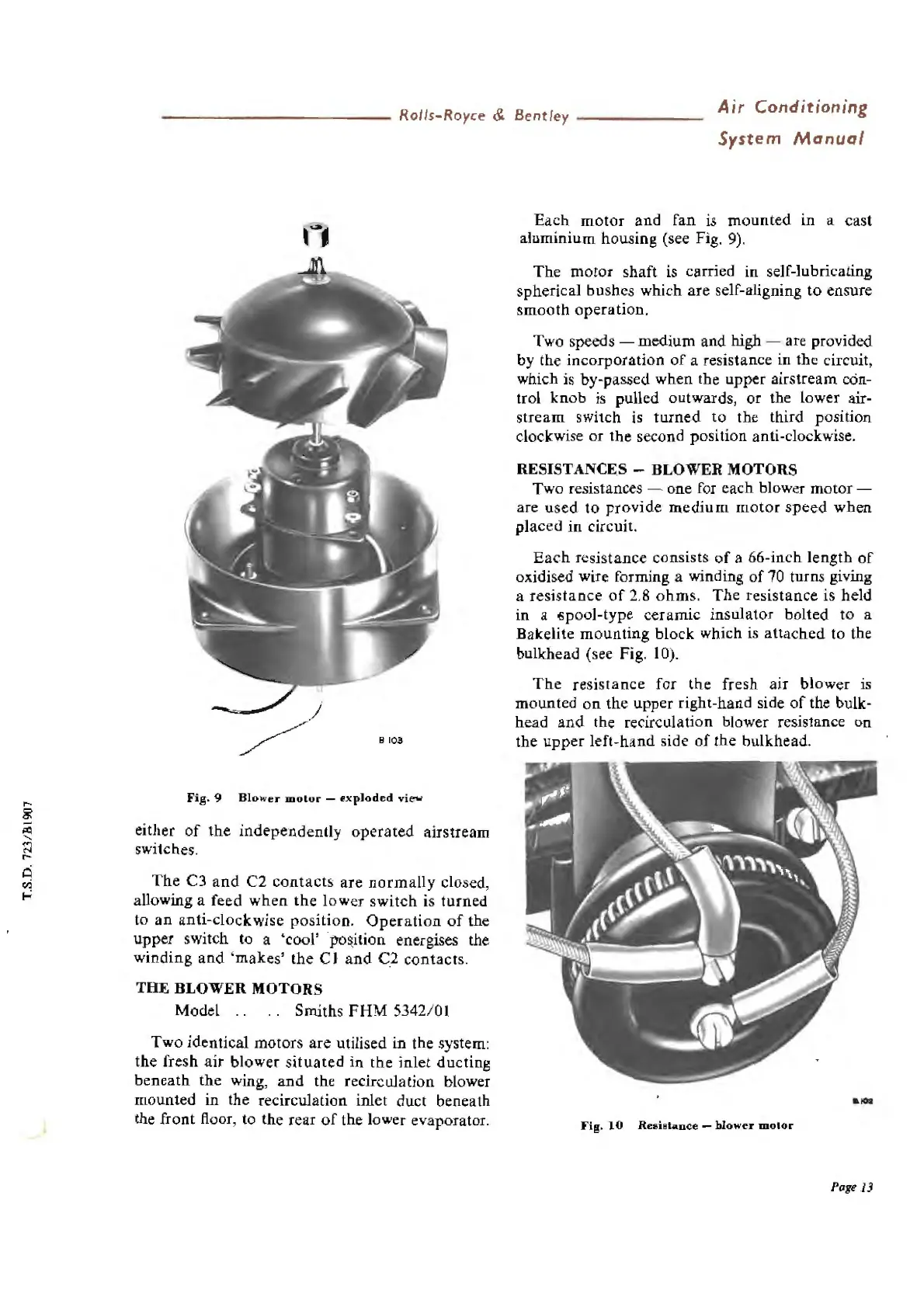
RESISTANCES - BLOWER MOTORS
Two resistances - one for each blower
motor
-
are
u
sed
to
provide
medium
mot
or
speed
when
placed
in
circuit.
Each
resistance consists
of
a 66-inch
length
of
oxidised wire forming a winding
of
70
turns giving
a resistance
of
2.8 ohms.
The
resista
nce
is held
in
a ~pool-type ceramic insulator bolted to a
Bakelite mounting block which
is
attach
ed to the
bulkhead (see Fig.
IO
).
The
resistance
for
the
fresh air
blower
is
mounted
on
the upper right-hand side
of
the bulk-
head
and
the recirculation
bl
ow
er
resistance on
the
upper
left-ha
nd
side
of
the bulkhead.
Fig.
10
Reai•
tanc
e -
blow
er
motor
Poge
13