Do you have a question about the Ropex RESISTRON RES-402 and is the answer not in the manual?
Defines the specific applications and risks of using the RESISTRON® temperature controllers.
Explains the importance of heatsealing band properties like TCR for controller operation.
Details requirements for the impulse transformer and its safe installation.
Specifies the use of original ROPEX current transformers for system integrity and function.
Highlights the mandatory use of ROPEX line filters for EMC compliance and proper installation.
Outlines recommended inspections and cleaning procedures for the controller.
Provides guidelines for environmentally sound disposal of the device according to EU directives.
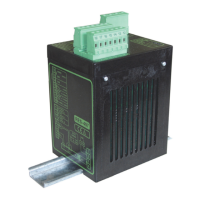
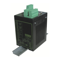
Step-by-step guide for installing the RESISTRON® temperature controller safely and correctly.
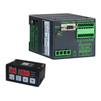
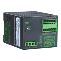
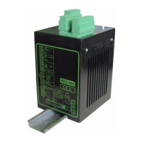
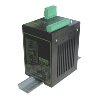
Illustrates the physical connections and placement for optimal controller installation.
Details the power supply connections, including over-current protection and line filter integration.
Explains the purpose and correct wiring of line filters for EMC compliance.
Specifies the integral role and correct connection of the ROPEX current transformer.
Specifies the requirement and protection of the 24VDC auxiliary voltage supply.
Provides a visual representation of the controller's electrical connections and system integration.
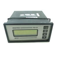
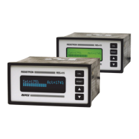
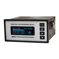
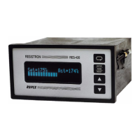
Identifies key components, terminals, LEDs, and buttons on the controller's front panel.
Explains controller configuration, including DIP switch settings for voltage/current and AUTORANGE.
Covers replacing the heatsealing band and performing the initial "burn-in" procedure.
Outlines the steps for initial controller startup and restart after band replacement.
Identifies and explains the function of LEDs, buttons, and terminals on the controller.
Describes the two methods for setting the desired heatsealing temperature.
Explains the analog output signal representing the actual measured temperature.
Details the AUTOCAL function for automatic zero point calibration and its activation.
Explains the function of the "START" signal to initiate the heating and control process.
Describes how the "RESET" signal aborts cycles, clears errors, and initiates internal resets.
Covers the diagnostic interface and the ROPEX visualization software for system monitoring.
Explains how system faults are indicated via LED status and alarm output signals.
Lists and explains error messages indicated by the "ALARM" LED.
Identifies common fault areas and their potential causes within the system.
| Brand | Ropex |
|---|---|
| Model | RESISTRON RES-402 |
| Category | Temperature Controller |
| Language | English |