ROPEX Industrie-Elektronik GmbH Tel.: +49 (0)7142-7776-0 E-Mail: info@ropex.de
Adolf-Heim-Str. 4 Fax: +49 (0)7142-7776-211 Internet: https://ropex.de
74321 Bietigheim-Bissingen (Germany) Data subject to change
27.7.20 Version 1
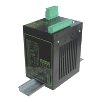
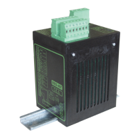
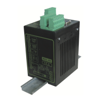
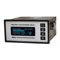
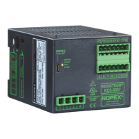
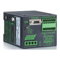
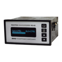
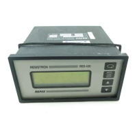
RES-420
Important features
• Microprocessor technology
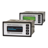
• LC display (green), 4 lines, 20 characters, (multilingual)
Alternatively:
VF display (blue), 4 lines, 20 characters, (multilingual)
• Automatic zero calibration (AUTOCAL)
• Automatic optimization (AUTOTUNE)
• Automatic configuration of the secondary voltage and current ranges
(AUTORANGE, as of software revision 100)
• Automatic phase angle compensation (AUTOCOMP, as of software revision 100)
• Automatic frequency adjustment
• Large current and voltage range
• Booster connection as standard
• Heatsealing band alloy and temperature range selectable
• Alarm function with fault diagnosis
Identical design to and compatible with RES-210, -211, -220, -221
Operating
Instructions