EasyManua.ls Logo

Ropex Resistron RES-5011 User Manual

Ropex Resistron RES-5011
76 pages
To Next Page IconTo Next Page
Page #1 background imageLoading...
Page #1 background image
ROPEX Industrie-Elektronik GmbH Tel.: +49 (0)7142-7776-0 E-Mail: info@ropex.de
Adolf-Heim-Str. 4 Fax: +49 (0)7142-7776-211 Internet: https://ropex.de
74321 Bietigheim-Bissingen (Germany) Data subject to change
7.11.19 Version 2
RESISTRON
RES-5011
Important features
Complete control via EtherNet/IP
TM
interface (2 x RJ-45)
Automatic zeroing (AUTOCAL)
Automatic optimisation (AUTOTUNE)
Automatic configuration of the secondary voltage and current range (AUTORANGE)
Automatic phase correction (AUTOCOMP)
Automatic frequency adaptation
Booster output
Analogue output 0…10 VDC for ACTUAL temperature
Alarm function with error diagnosis
Heating element alloy and temperature range can be selected
Wide voltage range for the use of 110…415 V
Eight channels for administration of various calibration values
Micro-USB interface for ROPEXvisual
®
cULus approval
Operating
instructions
Question and Answer IconNeed help?

Do you have a question about the Ropex Resistron RES-5011 and is the answer not in the manual?

Ropex Resistron RES-5011 Specifications

General IconGeneral
Number of Inputs1
OutputRelay
Supply Voltage24 V AC/DC
Display TypeLED
Operating Temperature0 to 50 °C

Summary

Revision List

General Information

2.2 Intended Use and Safety

Specifies approved applications, limitations, and general safety information for the controller.

2.3 Heatsealing Band Requirements

Details requirements for heatsealing bands for reliable and safe operation.

2.7 Standards and CE Marking

Lists standards and directives the controller complies with, and CE marking implications.

Use

Application Areas

Lists common applications for the RESISTRON controller in sealing and cutting thermoplastics.

Functional Principle

Device Features

Mounting and Installation

6.1 Installation Sequence

Step-by-step guide for the initial installation of the RESISTRON temperature controller.

6.3 Power Supply

Details the electrical power supply requirements and safety considerations.

6.6 Wiring Diagram (Standard)

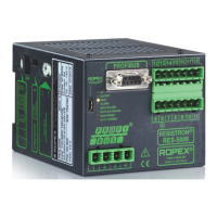
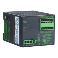
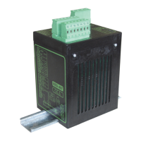
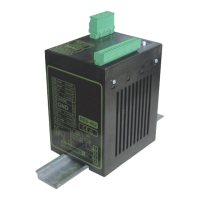
Shows the standard wiring connections for the RESISTRON controller.

6.7 Wiring Diagram with Booster Connection

Illustrates wiring for systems requiring a booster connection.

Startup and Operation

7.1 Device Overview

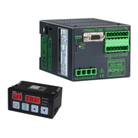
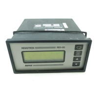
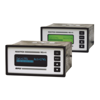
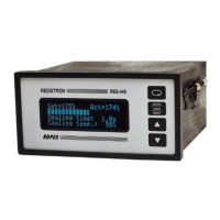
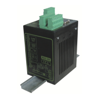
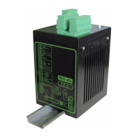
Identifies the main components and interfaces of the RESISTRON controller.

7.2 Device Configuration

Explains how to configure the controller's settings via switches and software.

7.4 Startup Procedure

Outlines the steps for initial power-up, calibration, and startup of the controller.

Device Functions

8.1 LEDs and Controls

Describes the meaning of the device's LEDs and their operating states.

8.2 EtherNet/IP™ Communication

Details how the controller communicates via the EtherNet/IP™ interface.

8.5 Input Data

Explains the data sent from the scanner to the RESISTRON controller.

8.6 Output Data

Describes the data sent from the RESISTRON controller to the scanner.

8.7 Parameter Object

Lists and describes the device's configurable parameters and their attributes.

8.8 Integrated Web Server

Provides access to status information and parameters via a web interface.

8.19 Error Messages

Provides a comprehensive list of error codes and their meanings.

8.20 Fault Areas and Causes

Helps identify and troubleshoot specific fault areas and their root causes.

Factory Settings

Default Configuration Parameters

Outlines the default factory settings for key controller parameters and functions.

Technical Data

Technical Specifications

Provides detailed electrical, environmental, and physical specifications of the controller.

Dimensions

Modifications

12.1 Modifications (MODs)

Describes available modifications for specialized heatsealing applications.

How to Order

Related product manuals