Do you have a question about the Ropex RESISTRON RES-5008 and is the answer not in the manual?
Explains the use of warning notices and signal words to indicate risks of injury or damage.
General warnings about following instructions and professional work to avoid injuries and damage.
Details the qualifications required for personnel performing installation, operation, and maintenance.
Details requirements for the heating element, including positive temperature coefficient (TCR).
Lists key features like AUTOCAL, AUTOTUNE, AUTORANGE, AUTOCOMP, and USB interface.
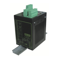
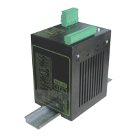
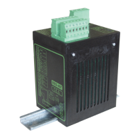
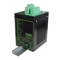
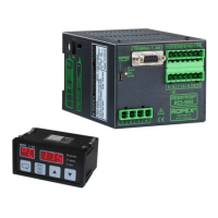
Provides a step-by-step guide for mounting and installing the controller and terminal.
Details mains connection requirements, including overcurrent devices and line filters.
Explains the process of configuring the device, including switching off the regulator first.
Covers the burn-in process for new heating elements and procedures for changing them.
Outlines rules for commissioning, emphasizing safety and qualified personnel.
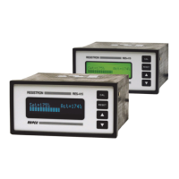
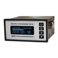
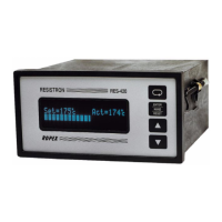
Identifies and explains the LEDs, display, and operating keys on the controller and terminal.
Explains how to set the sealing temperature and the valid range.
Details the AUTOCAL function for adapting the controller to system signals and heating element resistance.
Explains how the START signal initiates heating to the setpoint temperature.
Describes activating temperature diagnosis to check actual temperature against tolerance bands.
| Brand | Ropex |
|---|---|
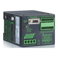
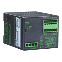
| Model | RESISTRON RES-5008 |
| Category | Temperature Controller |
| Language | English |