Do you have a question about the Ropex Resistron RES-407 and is the answer not in the manual?
Details on copyright protection for the document's content, including texts and graphics.
Specifies the approved applications for RESISTRON temperature controllers and highlights risks of misuse.
Explains the requirements for heatsealing bands, including TCR specifications, and the importance of correct selection.
Details specifications and safety requirements for the necessary impulse transformer for proper system operation.
Information on the integral current transformer, emphasizing the use of original ROPEX models for correct functionality.
Mandatory use of ROPEX line filters for EMC compliance and protection against line disturbances.
Recommends regular inspection of terminals and cleaning with dry compressed air; advises on dust/dirt prevention.
Instructions for storing and transporting the device in its original packaging and performing a visual inspection.
Guidelines for environmentally sound disposal of the device according to EU directives.
Step-by-step guide for installing the RESISTRON temperature controller, including safety precautions.
Visual guide illustrating the connection steps for the heatsealing element, transformer, and controller.
Details on power supply connections, over-current protection, line filter, and impulse transformer wiring.
Explanation of the line filter's role in EMC compliance and connection instructions.
Information on connecting the PEX-W4/-W5 current transformer to the controller.
Specifies the requirement for a 24VDC auxiliary voltage for isolated inputs and outputs.
Comprehensive wiring diagram for the standard RES-407 controller configuration.
Wiring diagram illustrating the connection for the booster modification (MOD 26).
Wiring diagrams for specific signal outputs (MOD 40/MOD 46).
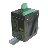
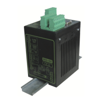
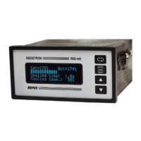
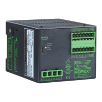
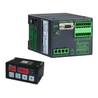
Identifies the main components and connection terminals of the RESISTRON RES-407 controller.
Instructions for configuring the controller using DIP switches and plug-in jumpers.
Procedure for replacing heatsealing bands and the 'burn-in' process for new bands.
Step-by-step guide for the initial startup of the RESISTRON temperature controller.
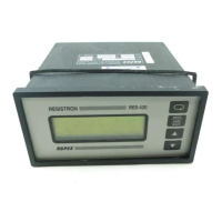
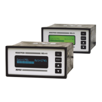
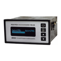
Description of front panel LEDs and their indications during operation and calibration.
Methods for setting the desired heatsealing temperature via analog input or potentiometer.
Explains the analog output signal representing the actual temperature and its relation to voltage.
Details the AUTOCAL function for automatic zero point adjustment and prerequisites for its activation.
Describes the function of the START signal to initiate heating and control process.
Explains the RESET signal's function to abort cycles, reset error messages, and initiate initialization.
Information on setting the measuring impulse length parameter via visualization software.
Explains the AUTOCOMP feature for compensating phase angle displacement in special applications.
Describes the temperature diagnosis feature checking actual temperature against settable tolerance bands.
Details the heatup timeout feature, monitoring the time to reach 95% of the set temperature.
Information on connecting to the diagnostic interface for system diagnostics and process visualization.
Overview of system monitoring features and alarm output signals for fault diagnosis.
Lists error codes, their corresponding voltage outputs, causes, and corrective actions.
Diagrams and tables correlating fault areas with specific causes and troubleshooting steps.
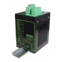
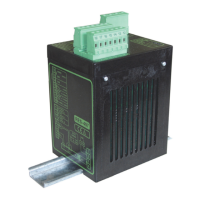
Describes the physical construction, mounting rail compatibility, and dimensions of the controller.
Specifies the supported AC line voltage ranges for different controller versions.
Details the line frequency range and automatic adjustment capabilities.
Specifies the 24VDC auxiliary voltage requirements and current input characteristics.
Information on settable temperature ranges and coefficients for various heatsealing band alloys.
Technical specifications for the analog input used for set point selection.
Technical specifications for the analog output signal representing the actual temperature.
Specifies the internal reference voltage provided by the controller.
Defines the voltage levels for digital inputs and outputs.
Technical details for specific switching output signals provided by modifications.
Specifies the characteristics and behavior of the alarm output signal.
Defines the maximum load capacity related to the impulse transformer's primary current.
Indicates the maximum power consumption of the controller.
Specifies the permissible ambient temperature range for operating the controller.
Details the IP rating indicating the controller's protection against solids and liquids.
Provides clearance recommendations for installing multiple controllers on a top hat rail.
States the weight of the controller, including connector plug-in parts.
Specifies the material used for the controller's housing.
Information on suitable cable types, cross-sections, and connection requirements.
Amplifier for low secondary voltages, suitable for short or low-resistance heatsealing bands.
Inverts the alarm signal output, changing HIGH/LOW states for alarm conditions.
Additional terminal for connecting an external switching amplifier (booster) for high primary currents.
Additional rotary coding switch for selecting heatsealing band alloys and temperature ranges (older versions).
Provides a terminal for a "Temperature reached" signal, activated when temp. exceeds 95% of setpoint.
Adds a "Temperature OK" signal based on settable tolerance bands around the setpoint.
| Mounting | Panel mounting |
|---|---|
| Input | Thermocouples |
| Output | Relay |
| Control Mode | PID |
| Supply Voltage | 100-240 V AC |
| Display | 7-segment LED |