6
VIA EMILIA OVEST 915/A - MODENA - I
C.P. 310 - 41100 MODENA
059 33 02 88
Fax 059 82 77 74
info@rossi-group.com
www.rossi-group.com
INSTALLATION AND MAINTENANCE INSTRUCTIONS UT. D 153 rev. 0
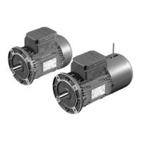
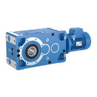
STANDARDFIT COAXIAL GEARMOTORS
Waste disposal: (follow the existing dispositions and laws in
matter of waste and environmental protection):
– exhausted oils must be recycled and treated according to te
existing dispositions;
– metal materials must be wasted as scraps and parted in categories: cast
iron (housing and gear reducer cover), steel (shafts, gear pairs and bear-
ings), aluminium (plugs);
– not ferrous materials (seal rings and caps) must be correctly wasted.
The paragraphs marked with present symbol contain disposi-
tions to be strictly respected in order to assure personal safety
and to avoid any heavy damages to the machine or to the sys-
tem (e.g.: works on live parts, on lifting machines, etc.); the
responsible for the installation or maintenance must scrupulously follow all
instructions contained in present handbook.
1 - General safety instructions
Gearmotors present dangerous parts because they may be:
– live;
– at temperature higher than +50 °C;
– rotating during the operation;
– eventually noisy (sound levels > 85 dB(A)).
An incorrect installation, an improper use, the removing or disconnection of
protection devices, the lack of inspections and maintenance, improper con-
nections may cause severe personal injury or property damage. Therefore
the component must be moved, installed, commissioned, handled, control-
led, serviced and repaired exclusively by responsible qualified person-
nel i.e. people who, in relation to their training and knowledge about existing
standards, dispositions, safety guard instructions and running conditions,
have been authorized, by the person responsible for plant safety, to follow
the required operations and are able to recognized and to avoid the possi-
ble connected danger (definition to IEC 364).
It is recommended to pay attention to all instructions of present handbook,
all instructions relevant to the system, all existing safety laws and standards
concerning correct installation.
Attention! Components in non-standard design or with constructive varia-
tions (identified by the initials stated in the proper field of the name plate,
see fig. 1) may differ in the details from the ones described here following
and may require additional information.
Attention! For the installation, use and maintenance of the electric motor
(standard, brake or non-standard motor) and/or the electric supply device
(frequency converter, soft-start, etc.) and accessories, if any consult the
attached specific documentation. If necessary, require it or visit our web-site
«
www.rossi-group.com
».
Attention! For any clarification and/or additional information consult ROSSI
MOTORIDUTTORI and specify all name plate data.
Gearmotors of present handbook are normally suitable for installations in
industrial areas: additional protection measures, if necessary for different
employs, must be adopted and assured by the person responsible for the
installation.
IMPORTANT: the components supplied by ROSSI MOTORIDUT-
TORI must be incorporated into machinery and should not be com-
missioned before the machinery in which the components have
been incorporated conforms to:
– Machinery directive 98/37/EEC; in particular, possible safety
guards for shaft ends not being used and for eventually acces-
sible fan cover passages (or other) are the Buyer’s responsi-
bility;
– «Electromagnetic compatibility (EMC)» directive 89/336/EEC
and subsequent updatings.
When operating on gearmotor or on components connected to it the
machine must be at rest: disconnect motor (including auxiliary
equipments) from power supply, gear reducer from load, be sure
that safety systems are on against any accidental starting and, if
necessary, pre-arrange mechanical locking devices (to be removed
before commissioning).
If deviations from normal operation occur (temperature increase,
unusual noise, etc.) immediately switch off the machine.
The products relevant to this handbook correspond to the technical
level reached at the moment the handbook is printed. ROSSI MO-
TORIDUTTORI reserves the right to introduce, without notice, the
necessary changes for the increase of product performances.
2 - Operating conditions
Gear reducers are designed for industrial applications according to
name plate data, at ambient temperature 0 +40 °C (with peaks at
-10 °C and +50 °C), maximum altitude 1 000 m.
Not allowed running conditions: application in aggressive environ-
ments having explosion danger, etc. Ambient conditions must com-
ply with specifications stated on name plate.
3 - How supplied
3.1 - Receipt
At receipt verify that the unit corresponds to the one ordered and
has not been damaged during the transport, in case of damages,
report them immediately to the courier.
Avoid commissioning gear reducers and gearmotors, that are even
if slightly damaged.
3.2 - Name plate
Every gear reducer presents a name plate in anodised aluminium
containing main technical information relevant to operating and
constructive specifications and defining, according to contractual
agreements, the application limits (see fig. 1); the name plate must
not be removed and must be kept integral and readable. All name
plate data must be specified on eventual spare part orders.
3.3 - Painting
The gearmotors are externally coated with dual-compound epoxy
primer (prepainted) and finishing blue RAL 5010 water-soluble
enamel appropriate for resistance to normal industrial environments
and suitable for further coats of single-compound synthetic paints
(normally also dual-compound).
The gear case internal parts are coated with dual-compound epoxy
primer (pre-painted)
Index
1 - General safety instructions
2 - Operating conditions
3 - How supplied
3.1 - Receipt
3.2 - Name plate
3.3 - Painting
3.4 - Protections and packing
4 - Storing
5 - Installation
5.1 - General
5.2 - Fitting of components to shaft ends
6 - Lubrication
6.1 - General
6.2 - Mounting positions
6.3 - Plug position
7 - Commissioning
8 - Maintenance
8.1 - General
8.2 - Seal rings
8.3 - Motor assembly
8.4 - Bearings
9 - Sound levels
Table of tightening torques for fastening bolts
(foot, flange and caselids)
Gear reducer troubles: causes and corrective
actions
6
6
6
6
6
6
7
7
7
7
8
8
8
8
9
9
9
9
9
9
9
10
10
 Loading...