9
7 - Commissioning
Carry out an overall check, making particularly sure that the gear
reducer is filled with lubricant.
After a 200
400 h running period it is advisable to verify the gear
reducer fixing bolt tightness.
8 - Maintenance
8.1 - General
At machine rest, verify at regular intervals (more or less frequently
according to environment and use):
a) all external surfaces are clean and air passages to the gearmo-
tors are free, in order that cooling remains fully effective;
b) oil deterioration degree (check with cold gear reducer at rest);
c) the correct fastening screws tightening.
During the operation check:
–
noise level;
–
vibrations;
–
seals;
–
etc.
Attention!
After a running period, gear reducer is subject
to a light internal overpressure which may cause burning
liquid discharge. Therefore, before loosening plugs wait
until gear reducer has become cold; if not possible, take
the necessary protection measures against burning due to warm oil
contact. ln all cases, always proceed with great care.
In case of oil replacement it's recommended to clean gear reducer
internal parts using the same kind of oil that will be used for the new
filling. It is possible to use again the cleaning oil after previous filter-
ing by means of 60
m oil filter.
When dismounting the cap reset the sealing with adhesive on
cleaned and degreased mating surfaces.
Tighten cover lid bolts and plug with the torques stated in the table
at page 10.
8.2 - Seal rings
Duration depends on several factors such as dragging speed, tem-
perature, ambient conditions, etc.; as a rough guide; it can vary from
3 150 to 12 500 h.
It is always recommended that the seal rings are replaced with new
ones when they are removed or during periodic checks of gear
reducer; in this case, the new ring should be generously greased
and positioned so that the seal line does not work on the same point
of sliding contact as the previous ring.
Oil seals must be protected against heat radiation, also during the
shrink fitting of parts, if applicable.
8.3 - Motor assembly
For motor assembly simply observe the following instructions:
− ensure that the mating surfaces are machined under «standard»
rating (IEC 72.1; UNEL 13501-69; DIN 42955) at least;
− clean surfaces to be fitted, thoroughly;
− check, and if necessary, lower the parallel key so as to leave a
clearance of 0,1 ÷ 0,2 mm between its tip and the bottom of the
keyway of the hole; when shaft keyway is without end, lock the
key with a pin;
− check that the fit-tolerance of bore-and-shaft end (standard lock-
ing) is K6/j6; the length of the parallel key is to be at least 0,9 times
the face width of the pinion;
− ensure that motor bearings are equivalent to the ones shown in the
table (have a load coefficient) according to motor size;
Motor size
Drive end bearing
56
6001
63
6201
71
6202
80
6204
90S
6005
90L
6205
100, 112
6206 (
4 kW, 4 poles); 6306
132
6208 (
7,5 kW, 4 poles); 6308
− mount the spacer (with rubber cement; check that between key-
way and motor shaft shoulder there is a ground cylindrical part
of at least 1,5 mm) and the pinion (the latter to be preheated to
a temperature of 80 ÷100 °C) on the motor, locking the assembly
with either a bolt to the shaft butt-end, or a stop collar;
− mount the possible fitting-ring for motor centering onto gear re-
ducer motor mounting flange;
− lubricate the pinion toothing, and the sealing ring and its rotary
seating with grease, assembling carefully.
The replacement of a standard motor with a motor standardized
to IEC of the same power supplied by the Customer is possible
only for motors in mounting position B5.
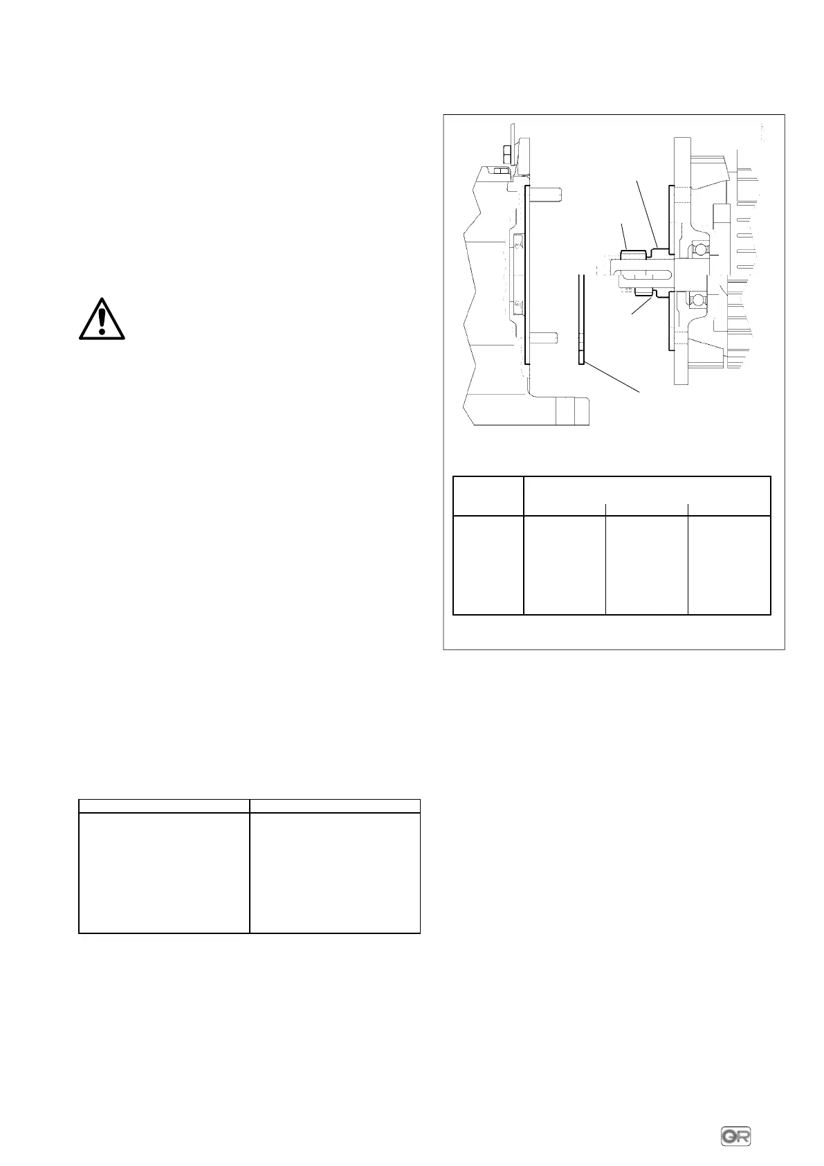
However, if need be and accepting a reduced machine duty
cycle, it is possible to replace the motors in mounting position B5
with power or motor power-to-size correspondence not
according to standard, B5R and B5S with motors standardized
to IEC of smaller power and size, if possible, having mating
dimensions as stated in the following fig. 7.
Motor size
Motor mounting position
1)
B5 B5R B5S
56
9 x 20 - 120 − −
63
11 x 23 - 140 9 x 20 - 120 −
71
14 x 30 - 160 11 x 23 - 140 −
80
19 x 40 - 200 14 x 30 - 160 −
90
24 x 50 - 200 19 x 40 - 200 −
100, 112
28 x 60 - 250 24 x 50 - 200 19 x 40 - 200
132
− 28 x 60 - 250 24 x 50 - 200
pinion
spacer
groove
for pulling
pinion
possible lifting
ring for motor
centering
1) Stated in designation (see ch. 3) and in motor name plate.
Fig. 7
Main motor maiting dimensions: shaft end Ø D x E
- flange Ø P
8.4 - Bearings
Since there are different types of bearings in a gear reducer (ball, or
cylindrical roller bearing) and each bearing works with different
loads and speeds depending on the input speed, the nature of the
load of the driven machine, the transmission ratio, etc., and with dif-
ferent lubricants (oil bath, oil splash, grease), it is not possible to
define any periodical maintenance and replacement of bearings in
advance.
If a precautional maintenance is required, undertake periodical
checks to verify noise level and vibration with the help of
appropiate diagniostic equipment and instruments. If the meas-
ured values worsen even slightly it is necessary to stop or gearmotor
and after having inspected inside the unit replace the bearings
which are subject to breakdown.
9 - Sound levels
The standard levels of sound power emission
L
WA
relevant to the
gearmotors of this catalogue, running at nominal load and speed,
fulfil the limits settled by VDI 2159 for gear reducers and EN 60034
for motors.
 Loading...