8
seal rings).
Gearmotors should be protected whenever possible and by appropri-
ate means from solar radiation and extremes of weather; weather
protection becomes essential when low speed shaft is vertically
disposed.
For ambient temperature greater than +40 °C or less than 0 °C,
consult ROSSI MOTORIDUTTORI.
5.2 - Fitting of components to shaft ends
It is recommended that the holes of parts keyed onto shaft ends
should be machined to K7 tolerance (H7 if load is uniform and
light).
Before mounting, thoroughly clean mating surfaces and lubricate
against seizure and fretting corrosion.
Attention! Installing and removal operations should b e carried out
with the aid of jacking screws and pullers using the tapped hole
at the shaft butt-end (see table in fig. 3) taking care to avoid
impacts and shocks which may irremediably damage the bear-
ings, the circlips, or other parts.
The couplings having a tip speed on external diameter up to 20
m/s must be statically balanced; for higher tip speeds they must be
dynamically balanced.
- 5.2 - Fitting of components to shaft ends
It is recommended that the holes of parts keyed onto shaft ends
should be machined to K7 tolerance (H7 it load is uniform and
light).
Before mounting, thoroughly clean mating surfaces and lubricate
against seizure and fretting corrosion.
Attention! Installing and removal operations should be carried out
with the aid of jacking screws and pullers using the tapped hole at
the shaft butt-end (see table in fig. 3) taking care to avoid impacts
and shocks which may irremediably damage the bearings, the
circlips.
The couplings having a tip speed on external diameter up to 20 m/s
must be statically balanced; for higher tip speeds they must be
dynamically balanced.
Shaft end
Fig. 3
UT.C 886
Gear
red
size
Ø D Ø d x l
0
20 k6 M 6 x 16
1
20 k6 M 6 x 16
2
25 k6 M 10 x 26
3
25 k6 M 10 x 26
4
30 k6 M 10 x 26
5
35 k6 M 12 x 32
6
35 k6 M 12 x 32
7
40 k6 M 16 x 40
l
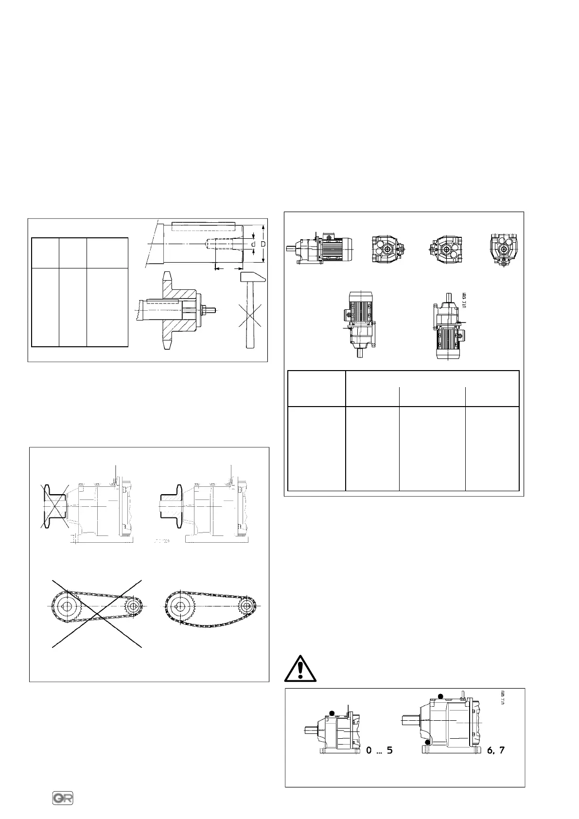
Where the transmission link between gear reducer and machine or
motor generates shaft end loads, (see fig. 4), ensure that:
– loads do not rise above catalogue values;
– transmission overhang is kept to a minimum;
– gear-type transmissions must guarantee a minimum of backlash
on all mating flanks;
– drive-chains should not be tensioned (if necessary – alternating
loads and/or motion – foresee suitable chain tighteners);
– drive-belts should not be over-tensioned.
UT.C 117
Fig. 3
Incorrect Correct
Incorrect Correct
6 - Lubrication
6.1 - General
Gearmotors are supplied FILLED WITH synthetic OIL (KLÜBER
Klübersynth GH 6-220, MOBIL Glygoyle 30, SHELL Tivela Oil S 220)
providing lubrication «for life» – assuming pollution-free surround-
ings – for gear pairs and bearings (oil-bath or splash lubrication).
However, for vertical mounting positions V5 and V6 upper bearings
are independently lubricated and are filled with special grease
(SHELL ALVANIA RL3 for ball bearings, KLÜBER STABURAGS NBU
8 EP for roller bearings) providing lubrication «for life», assuming
pollution-free surroundings. The same applies for motor bearings
and backstop devices when fitted to motors.
Ambient temperature range 0 ÷ 40 °C with peaks of -20 °C and
+50 °C.
Should there be either a possibility of lubricant contamination or a
particular type of duty-cycle, it is good policy to check on the state
of the lubricant (oil and possible grease) every year or 2 years and,
in any case, provide for lubricant replace every 2 or 4 years.
6.2 - Mounting position
Size
Oil quantity [l]
B3 B6, B7, B8, V6 V5
0
0,2 0,4 0,4
1
0,4 0,6 0,7
2
0,6 0,8 1
3
0,6 0,8 1
4
1,2 1,7 2
5
1,2 1,7 2
6
1,9 2,8 3,3
7
2,3 3,2 3,8
B3 B6 B7
B8
V5 V6
Fig. 5
Unless otherwise stated, geamotors are supplied in mounting posi-
tion B3 (see fig. 5) which, being standard, is omitted from the
designation and from the nameplate.
The mounting position ordered affects the quantity of lubricant
which the gear reducer is filled with before delivering as well as
possible bearings with independent lubrication (see ch. 6.1)).
Important: be sure that the gearmotor is installed as per mounting
position ordered and stated on the name plate. If the gearmotor is
installed in a different mounting position verify, according to the
values given in the table in fig. 5, that the oil quantity does not
change; if so, adjust it consequently. Moreover, V5 and V6 vertical
mounting positions need the upper bearings to be lubricated with
special grease (see ch. 6.1).
6.3 - Plug position
Gearmotors are provided with 1 (sizes 0 … 5) or 2 plugs (sizes 6 and
7), made of light alloy, positioned as per figure below. No level plug
is supplied.
Attention! Before loosening the plugs waint until gear
reducer has become cold (see ch. 8).
Thread
Tightening
torque
G 1/8"
3,5 N m
Thread
Tightening
torque
G 1/4"
7 N m
 Loading...