7
3.4 - Protections and packing
Overhanging free shaft ends are treated with protective anti-rust
long life oil and protected with a plastic (polyethylene) cap.
Unless otherwise agreed in the order, products are adequately
packed: in carton pallet, wound with adhesive tape and strap or for
small dimensions and quantities in carton boxes wound with tape. If
necessary, gear reducers are conveniently separated by means of
anti-shock foam cells or of filling cardboard.
Do not stock packed products on top of each other.
4 - Storing
Surroundings should be sufficiently clean, dry and free from ex-
cessive vibrations (v
eff
0,2 mm/s) to avoid damage to bearings (ex-
cessive vibration should also guarded during transit, even if within
wider range) and ambient storage temperature should be 0 +40 °C:
peaks of 10 °C above and below are acceptable.
It's adivisable to rotate the shafts (some revolutions are sufficient)
every six months to prevent damage to bearings and seal rings.
Assuming normal surroundings and the provision of adequate pro-
tection during transit, the unit is protected for storage up to 1 year.
For a 2 year storing period in normal surroundings it is necessary to
pay attention also to following instruction:
– generously grease the sealings and the shafts.
For storages longer than 2 years or in aggressive surroundings or
outdoors, consult ROSSI MOTORIDUTTORI.
5 - lnstallation
5.1 - General
Before the installation, verify that:
– there were no damages during the storing or the transport;
– design is suitable to the environment (temperature, atmosphere,
etc.);
– electrical connection (power supply, etc.) corresponds to motor
name plate data;
– used mounting position corresponds to the one stated in name
plate (see ch. 6.2).
Attention! When lifting and transporting the gearmotor
use the eyebolt supplied on the gear reducer (except for
size 0) and not the one, if present, supplied on the motor.
Be sure that load is properly balanced and provide lifting
systems, and cables of adequate section.
Gearmotor max mass is shown in the following table, according to
the motor size.
Gear
red.
size
Gearmotor max mass [kg]
Motor size
56 63 71 80 90 100 112 132
0
10 12 15 − − − − −
1
− 13 16 20 − − − −
2
− 16 20 25 33 40 − −
3
− 17 20 25 33 40 − −
4
− 26 29 35 43 50 64 −
5
− 27 30 36 44 51 65 92
6
− − 44 49 57 64 78 105
7
− − 48 53 61 68 83 117
Be sure that the structure on which gearmotor is fitted is plane (max
flatness error 0,1), levelled and sufficiently dimensioned in order
to assure fitting stability and vibration absence (vibration speed v
eff
3,5 mm/s), keeping in mind all transmitted forces due to the
masses, to the torque, to the radial and axial loads.
The max dimensions of fixing screws of gear reducer feet are given
in the next table (see fig. 2). Apply bolts and screws class 8.8 or
higher (for tightening torques see table on page 10) .
Attention! Bearing life and good shaft and coupling
running depend on alignment precision between the
shafts. Carefully align the gearmotor with the driven
machine (with the aid of shims if need be), interposing flexible cou-
plings whenever possible.
Gear reducer size Long bolt Short bolt
UNI 5737-88 / UNI 5739-88 (l max)
0
M 6 x 22 M 6 x 22
1
M 8 x 30 M 8 x 25
2
M 8 x 35 M 8 x 30
3
M 8 x 35 M 8 x 30
4
M12 x 45 M12 x 40
5
M12 x 45 M12 x 40
6
M12 x 55 M12 x 50
7
M16 x 60 M16 x 55
long bolt or nut seating
short bolt or nut seating
Incorrect alignment may cause breakdown of shafts and/or bear-
ings (which may cause overheatings) which may represent heavy
danger for people.
Position the gearmotor so as to allow a free passage of air for cool-
ing both gear reducer and motor (especially at their fan side).
Avoid: any obstruction to the air flow; heat sources near the gear
reducer that might affect the temperature of cooling air and of gear
reducer (for radiation); insufficient air recycle and applications hinder-
ing the steady dissipation of heat.
Mount the gearmotor so as not to receive vibrations.
Mating surfaces (of gear reducer and machine) must be clean:
remove the eventual paint of gear reducer coupling surfaces using
a scraper or solvent.
When external loads are present use pins or locking blocks, if ne-
cessary.
When fitting gear reducer and machine it is recommended to use
locking adhesives on the fastening screws.
Before wiring-up the gearmotor make sure that motor voltage corre-
sponds to input voltage. If direction of rotation is not as desired,
invert two phases at the terminals.
If overloads are imposed for long periods or if shocks or danger of
jamming are envisaged, then motor-protection, electronic torque li-
miters, safety couplings, control units or other similar devices should
be fitted.
Usually protect the motor with a thermal cut-out however, where
duty cycles involve a high number of on-load starts, it is necessary
to utilise thermal probes for motor protection (fitted on the wiring);
magnetothermic breaker is unsuitable since its threshold must be
set higher than the motor nominal current of rating.
Connect thermal probes, if any, to auxiliary safety circuits.
Use varistors and/or RC filters to limit voltage peaks due to con-
tactors.
Whenever a leakage of lubricant could cause heavy damages,
increase the frequency of inspections and/or envisage appropriate
control devices.
In polluting surroundings, take suitable precautions against lubri-
cant contamination through seal rings or other.
For outdoor installation or in a hostile environment, protect gearmo-
tor with an anticorrosion paint; added protection may be afforded by
applying water-proof grease (especialIy around the rotary seating of
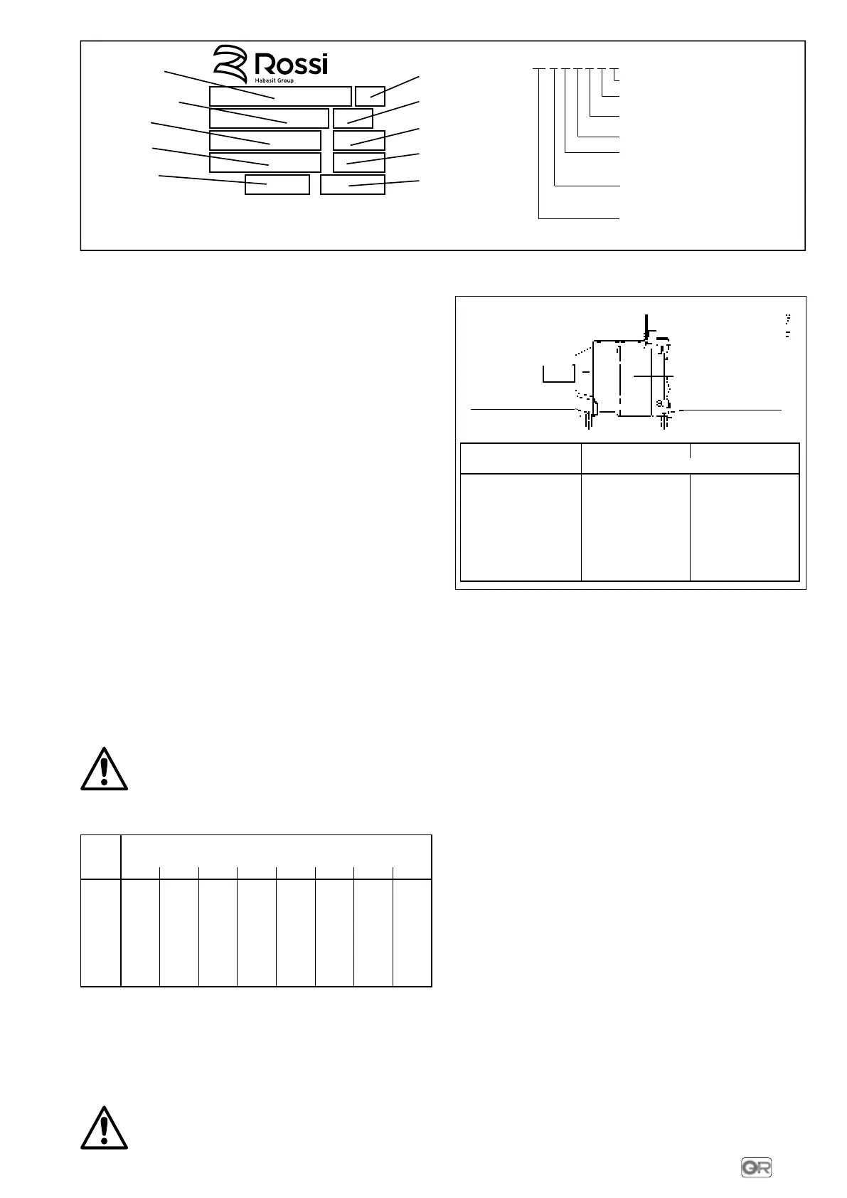
TIPO
TYPE
kW
kW
min
-1
P
N
(1400 min
-1
)
n
2
P
1
fs
i
Ø
Designation see
(scheme on the right)
Non-standard designs
Motor power
Gear motor
output speed
Gear reducer
nominal power
Two months and year of
manufacturing
Mounting position (when
differing from IM B3)
Gearmotor service
factor
Transmission ratio
Ø Motor shaft - Flange
Fig. 1 (for more information, see ROSSI MOTORIDUTTORI technical catalogue: consult us).
MR
3I 5 P C 3 E
DESIGN:
E
MODEL:
3
SHAFT
POSITION:
C
coaxial
MOUNTING:
P
foot
SIZE:
0 ... 7
TRAIN OF
GEAR:
2I
3I
2 cylindrical gear
pairs
3 cylindrical gear
pairs
MACHINE:
MR
gearmotor
Fig. 2
 Loading...