Do you have a question about the Rosslare AYC-F54 and is the answer not in the manual?
Details the waterproof, standalone convertible reader/controller, auto-detection, user capacity, and PIN length.
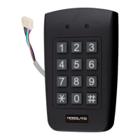
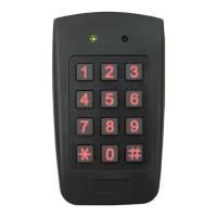
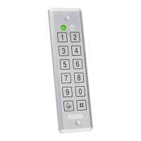
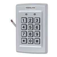
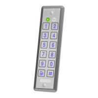
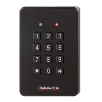
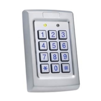
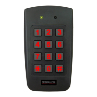
Lists AYC-F54, AYC-F64, AYC-G54, AYC-G64 models with their specific keypad and proximity capabilities.
Lists the AYC-Fx4/AYC-Gx4 unit, installation kit, and operating instructions.
Lists compatible host controllers and secure application appurtenances needed for installation.
Covers power supply, operating voltage, input current, LED control, tamper output, and cable distance to host.
Details operating temperature range, humidity levels, and weather resistance for outdoor use.
Lists the physical dimensions (height, width, depth) and weight of the units.
Highlights built-in proximity reader, backlit keypad, tamper sensor, lockout feature, buzzer, dual LEDs, and potted construction.
Provides instructions and diagrams for drilling mounting holes and securing the reader/controller unit to a surface.
Details the color-coded wires and their corresponding functions for reader and controller connections.
Illustrates wiring configurations for controller applications using secure application appurtenances and auxiliary loads.
Displays the wiring diagram for connecting the AYC-Fx4/AYC-Gx4 as a reader to a standard access control system.
Describes the reader's transmit mode, LED status, and how proximity cards or keypad entries are transmitted.
Explains that programming is done via the keypad-driven menu system and introduces default factory settings.
Guides users on selecting one of eight keypad transmission formats for data output.
Guides users on selecting one of three proximity card transmission formats: 26-Bit Wiegand, Clock & Data, or Wiegand Card + PIN.
Provides steps to change the 4-digit programming code used to access the device's settings.
Details the process for changing the 3-digit facility code, which affects card data transmission.
Provides instructions to erase all memory and restore factory default settings, including codes and configurations.
Offers a procedure to re-enter the programming mode using the default code if the programming code is forgotten.
Explains the three user levels (Normal, Secure, Master) and the two code memory slots for each user.
Details the three operating modes: Normal, Bypass, and Secure, and their characteristics.
Discusses configuring the controller's auxiliary input and output in ten different modes for various applications.
Describes how door alarms are generated via the Auxiliary Input, supporting Door-Forced and Door-Ajar conditions.
Explains how forcible opening or removal triggers a tamper event and its output signal.
Details how the unit enters lockout mode after multiple wrong code entries, deactivating the keypad and reader.
Describes the function of the Request to Exit (REX) button, which opens the door without a code.
Explains the role of Rosslare's secure application appurtenances for stand-alone access control units.
Introduces the keypad-driven programming menu system and lists default factory codes and settings.
Provides steps to enter programming mode by pressing the '#' key twice and entering the programming code.
Details how to exit programming mode by pressing the '#' key twice or via inactivity timeout.
Guides on changing the Lock Strike Code, used for testing the Lock Strike Relay during installation.
Guides on changing the Auxiliary Code, used for testing the Auxiliary Relay during installation.
Provides steps to change the 4-digit programming code used to access the device's settings.
Details how to change the code used to switch between Normal and Secure access modes.
Guides on modifying the Normal/Bypass code and configuring door chime settings.
Details how to configure fail-safe/secure operation, siren time, and lock strike release time.
Guides on defining the auxiliary input and output functions and settings.
Offers a table summarizing auxiliary modes, input functions, output activation, and settings for quick reference.
Offers brief descriptions of each auxiliary mode, referring to page 38 for implementation details.
Provides steps to configure the lockout feature, determining the number of wrong attempts and lockout duration.
Details how to enroll Primary and Secondary Codes for users, explaining their properties and access rights.
Provides methods for deleting Primary and Secondary Codes for users from the system.
Describes how to assign codes to activate Lock Strike or Auxiliary relays for users.
Guides on changing the PIN code length, which also resets all codes to factory defaults.
Instructions for recovering lost programming or normal/secure codes via default settings and programming mode.
Details the warranty period, covered products, and the process for making a claim.
Outlines the process for making a warranty claim, including product return and evaluation procedures.
Lists items and conditions not covered by the warranty, such as ancillary equipment and customer-induced damage.
States that the warranty is provided in lieu of all other warranties and excludes incidental or consequential damages.
Provides contact information for technical support across different global regions.
| Model | AYC-F54 |
|---|---|
| Type | Controller |
| Number of Doors | 1 |
| Power Supply | 12V DC |
| Operating Voltage | 12-24V DC |
| Communication | RS485 |
| Operating Humidity | 0% to 95% (non-condensing) |
| Relay Contact Rating | 5A @ 30VDC |
| Protection | Short Circuit |
| Weight | 160 g |