OPERATION AND TROUBLESHOOTING
TROUBLESHOOTING
! WARNING !
Using a Test Light may cause damage to the vehicle.
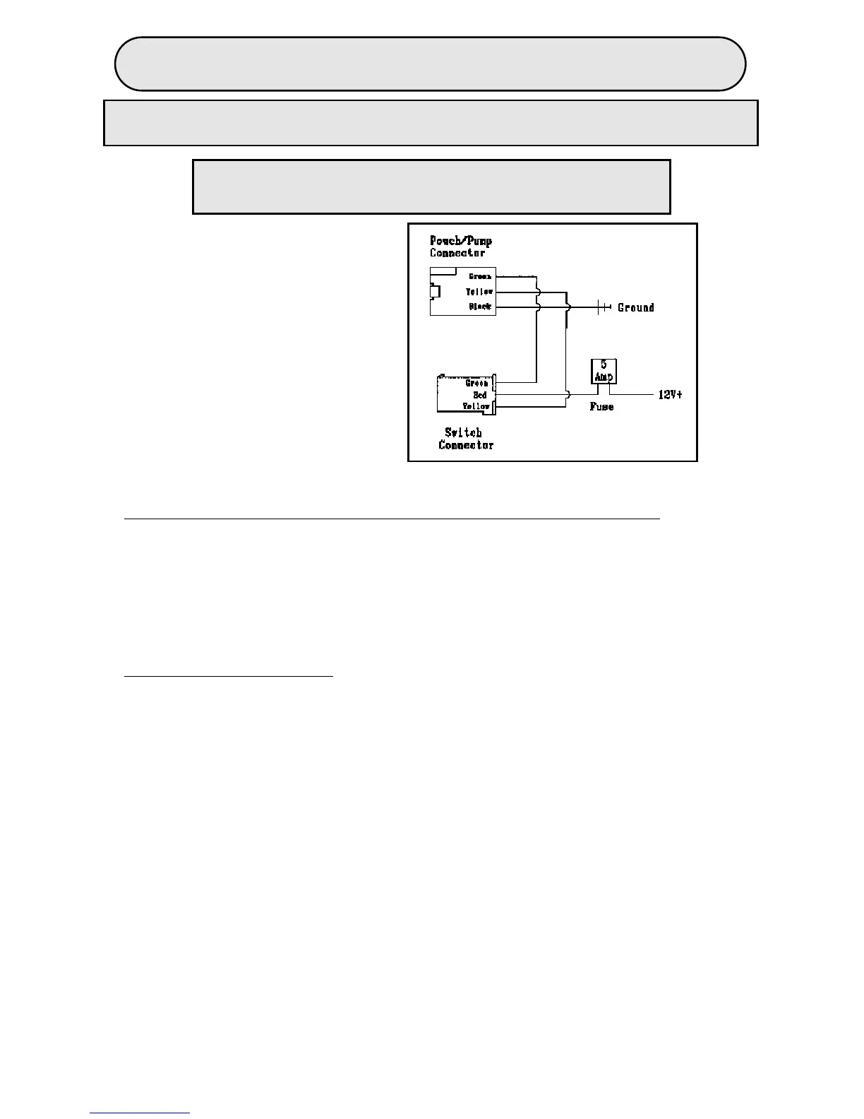
WIRING DIAGRAM
R = Red = Power
Y = Yellow = Valve
B = Black = Ground
GR = Green = Pump
RE-CONNECT NEGATIVE BATTERY CABLE.
1. PUMP OPERATIONAL BUT BLADDER IS NOT INFLATING/DEFLATING:
a. Not inflating:
Disconnect bladder from pump hose. Depress the high side of switch. Check if there
is air flow from the pump, approximately 2 psi.
No?- go to 2f. Yes?- replace bladder
b. Not deflating:
Disconnect bladder from the pump hose. Is air flow coming out of the bladder hose
when initially disconnected?
No?- go to 1a. Yes?- go to 2f.
2. PUMP NOT OPERATIONAL:
(See wiring diagram on page 6)
a. Check 5 Amp lumbar Fuse to power system. Replace fuse if needed.
b. Check 12 Volts Accessory vehicle Fuse. Replace fuse if needed.
c. Check harness Ground for continuity.
d. Check Vehicle power point for 12 Volts.
e. Check all connections. (pump & switch connector, special terminal, fuse splice...)
f. Unplug the switch from the harness and check voltage at the harness connection:
* For 12V GR= 0 Volts , R= 12 Volts , Y= 0 Volts. If bad replace harness, If good go to g.
g. Unplug the harness from the pump connector and check harness continuity:
GR at pump to GR at switch= closed circuit
Y at pump to Y at switch= closed circuit
B at pump to vehicle Ground= closed circuit,
If bad replace harness, if good go to 2h.
h. Check switch continuity with switch unplugged at the switch connector:
R to Y no activation= open circuit
low switch side activated= closed circuit
high switch side activated= closed circuit
R to GR no activation= open circuit
low switch side activated= open circuit
high switch side activated= closed circuit
If bad replace switch. If good replace pump/pouch system.
If your system still does not work properly, repeat troubleshooting 1 more time.
PAGE 7
 Loading...