6
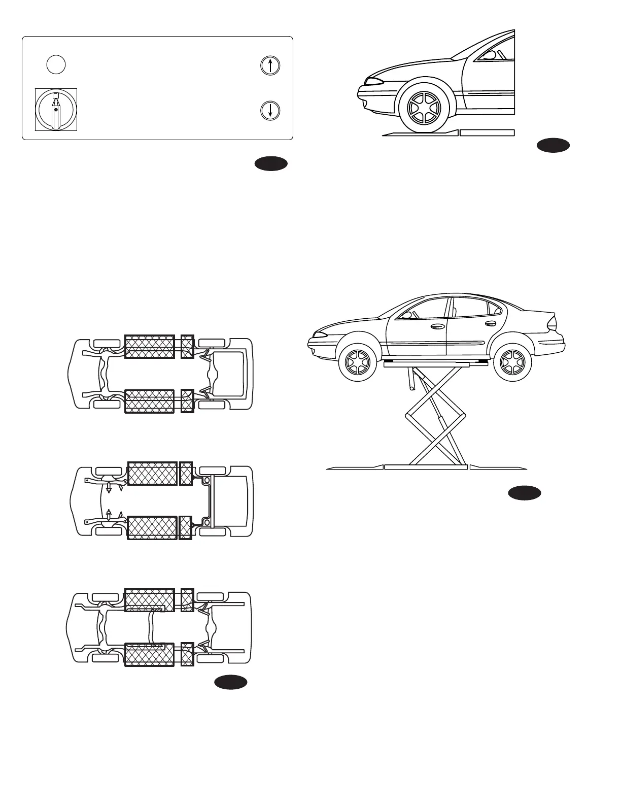
NOTE:Somevehiclesmayhavethemanufacturer'sService
Garage Lift Point locations identified by triangle shape marks
onit'sundercarriage(referenceANSI/SAEJ2184-1992).Also,
there may be a label located on the right front door lock face
showing specific vehicle lift points. If the specific vehicle
lift points are not identified, refer to the "Typical Lift Points"
illustrated herein. ALWAYS follow the operating instructions
supplied with the lift.
TypicalWheelSpottingPosition
Fig. 2
Fig. 1
Fig. 3
Fig. 4
1. Disconnect Switch
2. Raise Button
3. Lower Button
ON
1 3
2
A
Perimeter Frame
FrontFrontFront
Stub Frame
Unibody
 Loading...