Do you have a question about the Rotel RSX-1065 V02 and is the answer not in the manual?
Details amplifier power, THD, frequency response, S/N ratios, and tone controls.
Specifies usable sensitivity, S/N ratio, harmonic distortion, stereo separation, and output.
Lists sensitivity, S/N ratio, and output level for the AM tuner section.
Covers power consumption, requirements, weight, and dimensions.
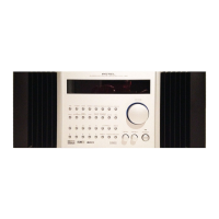
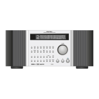
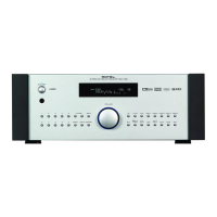
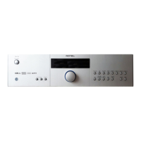
Illustrates and labels the front panel controls and display of the receiver.
Contains critical warnings regarding electric shock and exposure to rain or moisture.
Lists part numbers and descriptions for the FIP PCB assembly.
Lists part numbers and descriptions for the Front PCB assembly.
Lists part numbers and descriptions for the Power Amp PCB assembly.
Identifies panel parts, buttons, knobs, and LEDs for different color variants.
Details procedures for center, channel separation, and tuned level adjustments for FM.
Outlines VT, output level, and tuned level adjustments for the AM tuner.
Describes the method for adjusting power amplifier idling current after warm-up.
Provides a step-by-step guide for upgrading the RSX-1065 software via HyperTerminal.
Lists parts and their corresponding numbers for disassembly, including screws.
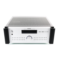
Provides a visual exploded view of the unit for disassembly reference.
Details the "FROM" and "TO" connections for various PCBs and connectors.
Shows the top and bottom views of the FIP PCB assembly.
Displays the top and bottom views of the SUB PCB assembly.
Shows the top and bottom views of the Digital 1 PCB assembly.
Displays the top and bottom views of the Digital Board 2 PCB assembly.
Shows the top and bottom views of the Video PCB assembly.
Displays the top and bottom views of the Amplifier PCB assembly.
Shows the top and bottom views of the Tuner PCB assembly.
Displays the top and bottom views of the Power Supply PCB assembly.
Illustrates the signal flow for the tuner section, including FM, AM, and PLL.
Shows the signal path for audio inputs, zone output, and recording.
Depicts the digital inputs, DACs, ADCs, and signal routing.
Illustrates the video signal paths for input, processing, and output.
Shows the FIP, main CPU, remote input, and interface connections.
Illustrates the power supply distribution and regulation.
Details the electronic circuit schematic for the Amplifier 2 PCB.
Details the electronic circuit schematic for the Amplifier 1 PCB.
Shows the detailed circuit schematic for the Digital 1 PCB.
Details the electronic circuit schematic for the Digital Board 2.
Shows the schematic for the Front Information Panel (FIP) circuit.
Illustrates the schematic for the front panel controls and interface.
Shows the circuit for selecting audio and video input sources.
Details the circuit for Zone 2 audio output and control.
Illustrates the circuit for component video signal processing.
Shows the primary power supply circuit schematic.
Details the main capacitor board schematic.
Illustrates the rectifier and fuse circuit schematic.
Shows the schematic for the auxiliary supply PCB.
Details the electronic circuit schematic for the Tuner board.
Shows the circuit for speaker output relays and terminals.
Details the electronic circuit schematic for the Video PCB.
| Channels | 5.1 |
|---|---|
| Total Harmonic Distortion (THD) | 0.05% |
| Input Sensitivity | 200 mV |
| Tuner Bands | AM/FM |
| Digital Sound Processor (DSP) | Yes |
| HDMI Switching | No |
| Video Conversion/Scaling | No |
| Inputs | 3 x Optical, 3 x Coaxial |
| Outputs | 1 x Subwoofer |
| Response Bandwidth | 10 Hz |
| Signal-To-Noise Ratio | 100dB |
| Input Impedance | 47 kΩ |
| Surround Sound Effects | Dolby Digital, DTS |
| Power Consumption | 500W |
| Power Output | 100 Watts per channel (8 Ohms, 20 Hz - 20 kHz, < 0.09% THD) |
| Frequency Response | 10 Hz - 100 kHz ±3 dB |