7 Installation
Installation and operation manual
19
RHYKOMB33AA
ROTEX HPU hybrid gas boiler module
4P353068-1B – 2014.02
The horizontal flue MUST be installed under a 3° fall towards the
boiler (50 mm per meter) and MUST be supported with a minimum
of 1 bracket at each meter length. Best recommended position of the
bracket is just before the joint.
INFORMATION
Flexible flue gas lines may NOT be used in horizontal
connection sections.
C
13
(1) C
33
(2) C
13
(1) C
33
(2)
60/100 60/100 Twin-80 Twin-80
L1 (m) L1 (m) L1 (m) L1 (m)
10 10 80 21
C
13
(1) C
33
(2) C
93
(4) C
53
(3)
80/125 80/125 80/125 80 60/100 60
L1 (m) L1 (m) L1 (m) L2 (m) L1 (m) L2 (m)
29 29 10 25 6 1
1 10
Special remark regarding C
53
: The maximum lengths for L1 and L2
are related to each other. First determine the length of L1; then
make use of the graph below to determine the maximum length of
L2. For example: if the length of L1 is 2 m, L2 can maximally be 8 m
long.
7
6
5
10
9
11
8
3
4
2
1
0
L2
L1
01234 675
L2=–1.8×L1+11.8
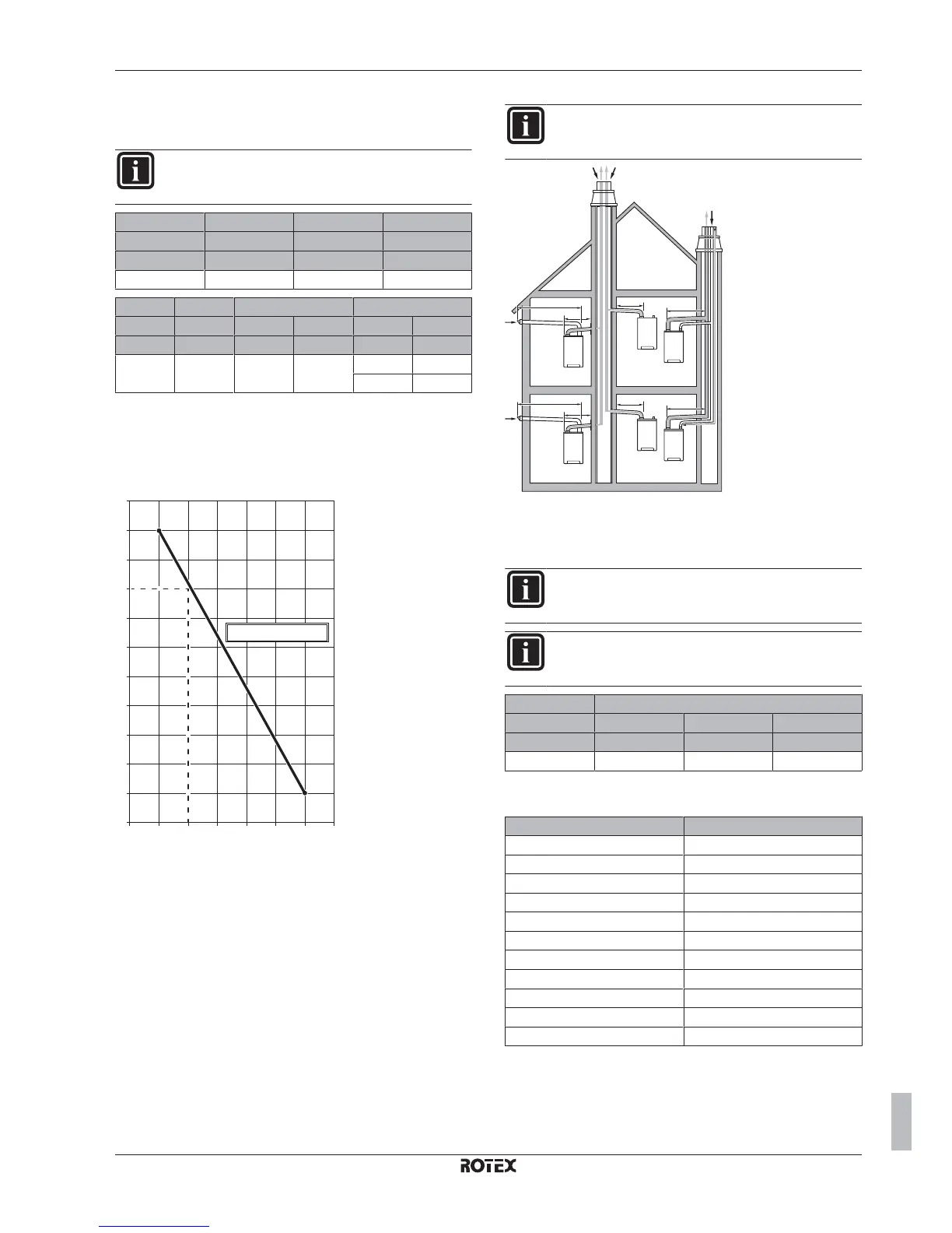
Multi-boiler installation
INFORMATION
All piping lengths in the tables below are maximum
equivalent piping lengths.
L1
L1
C
83
C
43
C
43
6
L2
5
C
83
6
L1
C
43
C
43
5
5
5
L1
L2
L1
L1
L2
The horizontal flue MUST be installed under a 3° fall towards the
boiler (50 mm per meter) and MUST be supported with a minimum
of 1 bracket at each meter length. Best recommended position of the
bracket is just before the joint.
INFORMATION
Flexible flue gas lines may NOT be used in horizontal
connection sections.
INFORMATION
The maximum lengths in the table below apply to each gas
boiler separately.
C
83
(6) C
43
(5)
Twin-80 60/100 80/125 Twin-80
L1+L2 (m) L1 (m) L1 (m) L1+L2 (m)
80 10 29 80
Special remark regarding C
83
: Refer to the table below for the
minimum diameters of the combined gas exhaust system.
Number of units Minimum Ø
2 130
3 150
4 180
5 200
6 220
7 230
8 250
9 270
10 280
11 290
12 300

 Loading...


