6 Technical data
Installation manual
10
RRLQ011~016CA
Outdoor unit for air to water heat pump
4P385895-1A – 2016.03
6 Technical data
Latest information can be found in the technical engineering data.
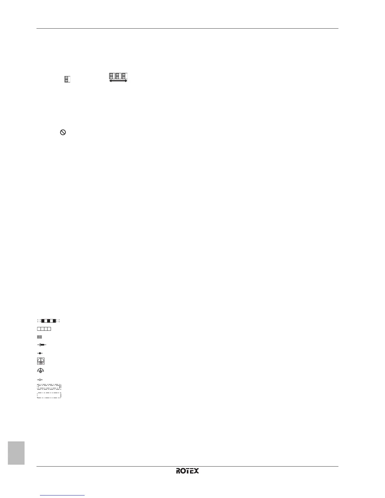
6.1 Service space: Outdoor unit
Single unit ( ) | Multiple units ( )
See figure 1 on the inside of the front cover.
A,B,C,D Obstacles (walls/baffle plates)
E Obstacle (roof)
a,b,c,d,e Minimum service space between the unit and obstacles A, B, C, D and E
e
B
Maximum distance between the unit and the edge of obstacle E, in the direction of obstacle B
e
D
Maximum distance between the unit and the edge of obstacle E, in the direction of obstacle D
H
U
Height of the unit
H
B
,H
D
Height of obstacles B and D
1 Recommended to prevent exposure to wind and snow.
Not allowed
6.2 Wiring diagram
6.2.1 Wiring diagram: Outdoor unit
The wiring diagram is delivered with the unit, located at the inside of
the service cover.
Notes:
1 This wiring diagram applies only to the outdoor unit.
2 Symbols (see below).
3 Symbols (see below).
4 Refer to the option manual for connecting wiring to X6A and
X77A.
5 Refer to the wiring diagram sticker (on the back of the service
cover) for how to use the BS1~BS4 and DS1 switches.
6 When operating, do not short-circuit protective device S1PH.
7 Colours (see below).
8 Refer to the service manual for instructions on how to set the
selector switches (DS1). The factory setting of all switches is
OFF.
9 Symbols (see below).
Symbols:
L Live
N Neutral
Field wiring
Terminal strip
Connector
Connector
Connection
Protective earth (screw)
Noiseless earth
Terminal
Option
Wiring dependent on model
Colours:
BLK Black
BLU Blue
BRN Brown
GRN Green
ORG Orange
RED Red
WHT White
YLW Yellow
Legend:
A1P~A4P Printed circuit board
BS1~BS4 Push button switch
C1~C4 Capacitor
DS1 DIP switch
E1H Bottom plate heater
E1HC Crankcase heater
F1U~F8U
(RRLQ_V3)
▪ F1U, F3U, F4U: Fuse (T 6.3 A /
250V)
▪ F6U: Fuse (T 5.0A / 250V)
▪ F7U, F8U: Fuse (F 1.0A / 250V)
F1U~F9U
(RRLQ_W1)
▪ F1U, F2U: Fuse (31.5A / 500V)
▪ F3U~F6U: Fuse (T 6.3A / 250V)
▪ F7U: Fuse (T 5.0A / 250V)
▪ F8U, F9U: Fuse (F 1.0A / 250V)
H1P~H7P (A2P)
(RRLQ_V3)
Light‑emitting diode (service monitor
orange)
H2P:
▪ Prepare, test: Flickering
▪ Malfunction detection: Light up
H1P~H7P (A1P)
(RRLQ_W1)
Light‑emitting diode (service monitor
orange)
HAP (A1P)
(RRLQ_V3)
Light‑emitting diode (service monitor
green)
HAP (A1P, A2P)
(RRLQ_W1)
Light‑emitting diode (service monitor
green)
K1M, K2M
(RRLQ_W1)
Magnetic contactor (main, upload)
K1R~K4R Magnetic relay
K10R, K11R
(RRLQ_V3)
Magnetic relay
L1R~L4R Reactor
M1C Motor (compressor)
M1F Motor (upper fan)
M2F Motor (lower fan)
PS Switching power supply
 Loading...