4 Installation
Installation manual
8
RRLQ011~016CA
Outdoor unit for air to water heat pump
4P385895-1A – 2016.03
4.5.1 About electrical compliance
RRLQ_V3
Equipment complying with:
▪ EN/IEC 61000‑3‑11
provided that the system impedance Z
sys
is
less than or equal to Z
max
at the interface point between the user's
supply and the public system.
▪ EN/IEC 61000‑3‑11 = European/International Technical
Standard setting the limits for voltage changes, voltage
fluctuations and flicker in public low-voltage supply systems for
equipment with rated current ≤75A.
▪ It is the responsibility of the installer or user of the equipment to
ensure, by consultation with the distribution network operator if
necessary, that the equipment is connected only to a supply
with a system impedance Z
sys
less than or equal to Z
max
.
▪ EN/IEC 61000‑3‑12 provided that the short-circuit power S
sc
is
greater than or equal to the minimum S
sc
value at the interface
point between the user's supply and the public system.
▪ EN/IEC 61000‑3‑12 = European/International Technical
Standard setting the limits for harmonic currents produced by
equipment connected to public low-voltage systems with input
current >16A and ≤75A per phase.
▪ It is the responsibility of the installer or user of the equipment to
ensure, by consultation with the distribution network operator if
necessary, that the equipment is connected only to a supply
with a short-circuit power S
sc
greater than or equal to the
minimum S
sc
value.
Model Z
max
Minimum S
sc
value
RRLQ011CAV3
RRLQ014CAV3
RRLQ016CAV3
0.22Ω 525kVA
RRLQ_W1
Equipment complying with EN/IEC 61000‑3‑12 (European/
International Technical Standard setting the limits for harmonic
currents produced by equipment connected to public low-voltage
systems with input current >16A and ≤75A per phase.).
4.5.2 Specifications of standard wiring
components
Component RRLQ_V3 RRLQ_W1
Power supply
cable
MCA
(a)
34.2A 16.3A
Voltage 230V 400V
Phase 1~ 3N~
Frequency 50Hz
Wire sizes Must comply with applicable
legislation
Interconnection cable Minimum cable section of
2.5mm² and applicable for
230V
Recommended field fuse 40A 20A
Earth leakage circuit breaker Must comply with applicable
legislation
(a) MCA=Minimum circuit ampacity. Stated values are
maximum values (see electrical data of combination with
indoor units for exact values).
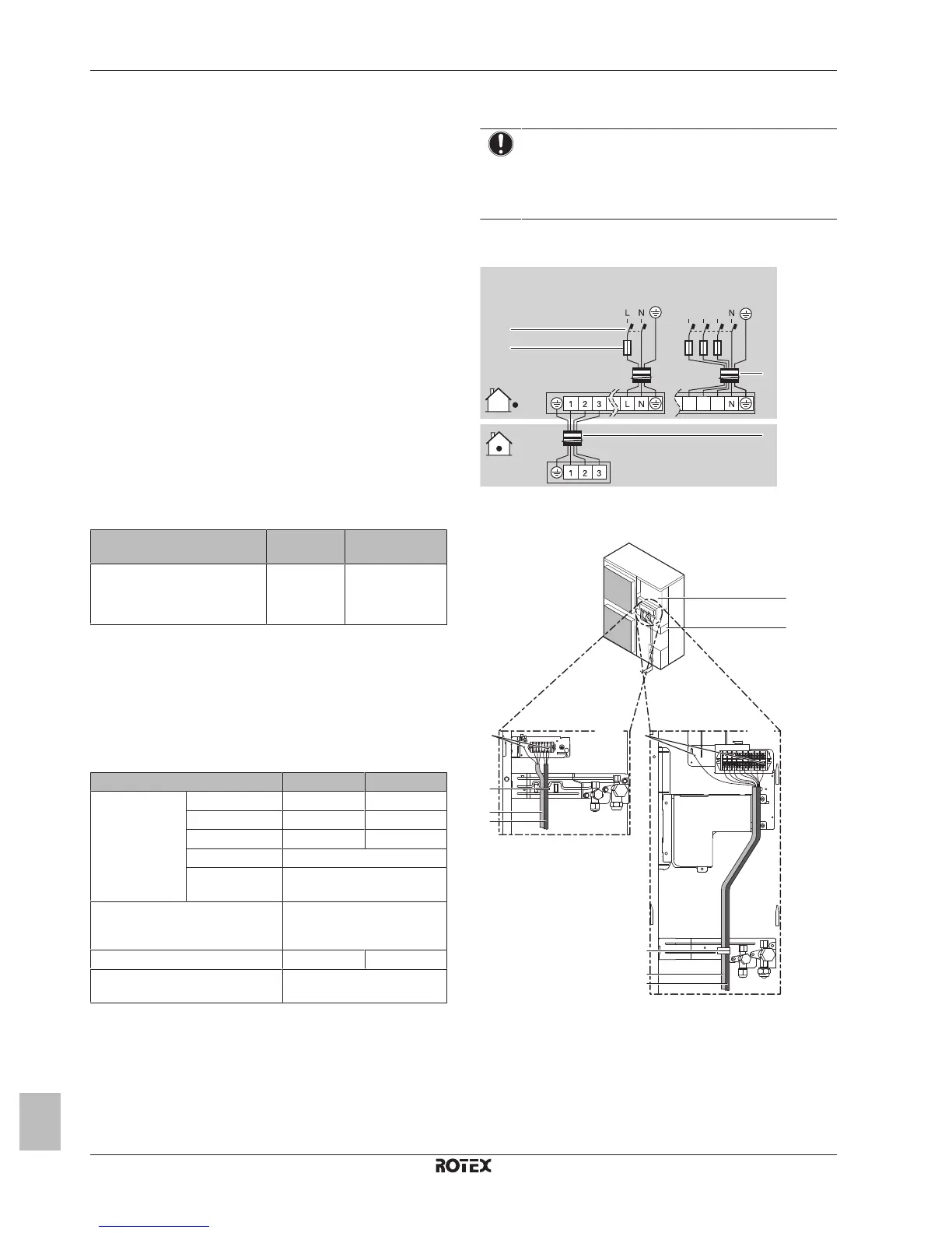
4.5.3 To connect the electrical wiring on the
outdoor unit
NOTICE
▪ Follow the wiring diagram (delivered with the unit,
located at the inside of the service cover).
▪ Make sure the electrical wiring does NOT obstruct
proper reattachment of the service cover.
1 Remove the service cover.
2 Connect the interconnection cable and power supply as follows:
c
b
a
d
V3
1~ 50 Hz
230 V
W1
3N~ 50 Hz
400 V
L1 L3L2
L1 L3L2
a Interconnection cable
b Power supply cable
c Earth leakage circuit breaker
d Fuse
a Switch box
b Stop valve attachment plate
c Earth
d Cable tie
e Interconnection cable
f Power supply cable
3 Fix the cables (power supply, interconnection cable and power
supply of the bottom plate heater (if applicable)) with a cable tie
to the stop valve attachment plate.
4 Route the wiring through the frame and connect it to it.
 Loading...