ROTORCOMP VERDICHTER Operating Manual - EVO
®
Line
3.2 [en] 07/2020
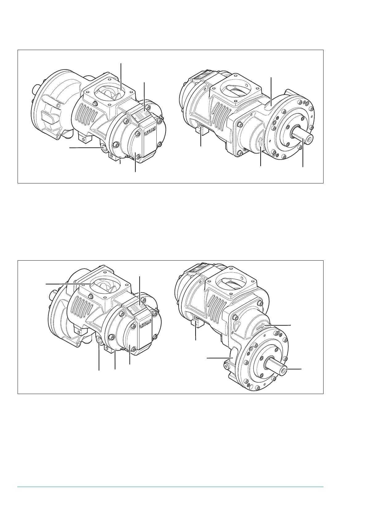
Figure 3-2 Screw compressor air end EVO9-G-V0 (horizontal transmission)
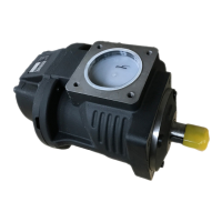
Figure 3-3 Screw compressor air end EVO9-G-V1 (vertical transmission)
1. Air inlet 6. Oil injection
2. Air outlet (see installation drawing) 7. Direction of rotation
3. End cover 8. Oil return line (non-return valve not integrated)
4. Drive shaft 9. Transmission
5. Nameplate
1. Air inlet 6. Oil injection
2. Air outlet (see installation drawing) 7. Direction of rotation
3. End cover 8. Oil return line (non-return valve not integrated)
4. Drive shaft 9. Transmission
5. Nameplate
5
1
3
4
7
2
6
8
9
5
1
3
4
7
2
6
8
9