Modbus Option Card Properties
Publication PUB091-004-00_0918 13 of 64
3.4 Inside a CVA actuator
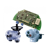
The single channel MFU is suitable for fitting into CVA actuators. When factory-fitted, the wiring
diagram will be CXX-40 (where X can be any value). This details the option card connections to the
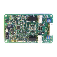
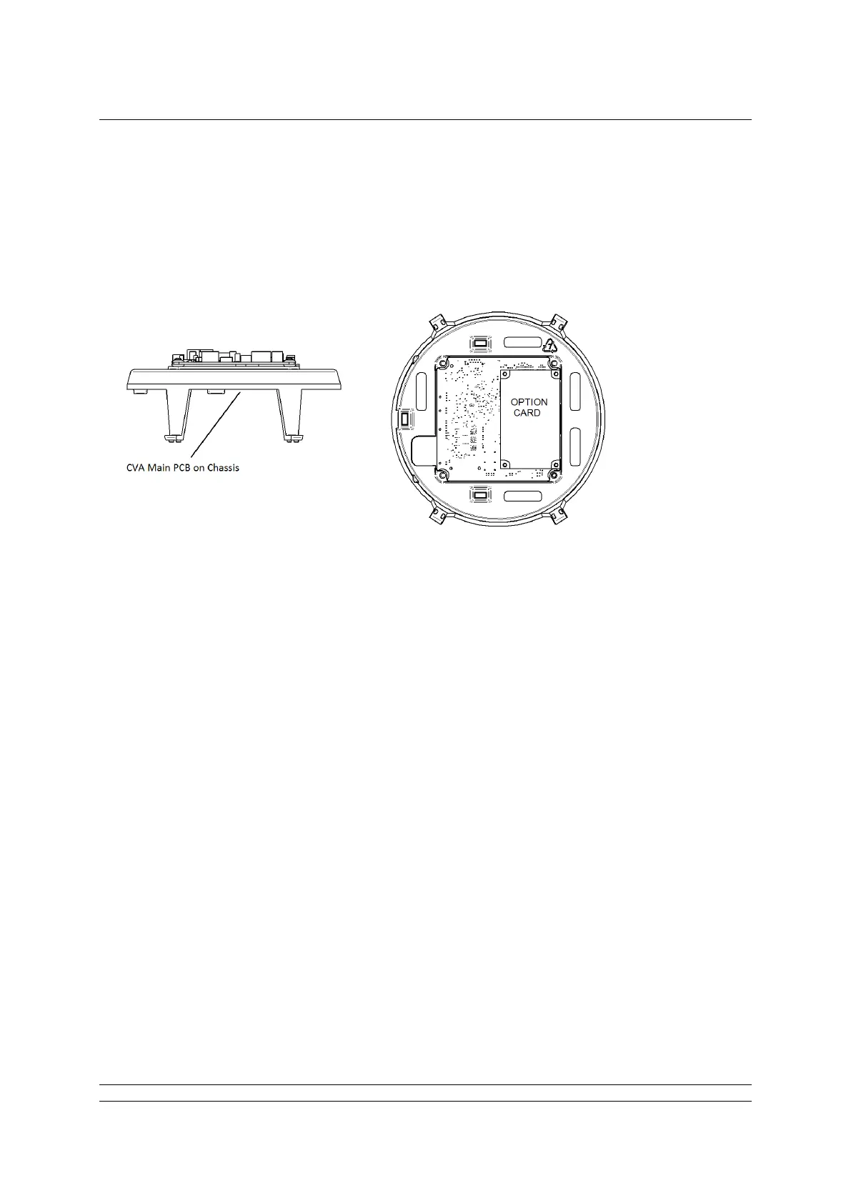
terminal bung. The MFU module is fitted in the only option board slot inside the CVA electrical housing
- on the underside of the Main PCB assembly. The MFU should be replaced or fitted only in a suitable
environment.
Fig 4: The MFU located on the underside of the control PCB in a CVA actuator
To fit an MFU card, begin by removing power from the actuator and wait until the LED on the selector
knob stops illuminating. This may take several minutes if a reserve power pack of capacitors is fitted.
Remove the six M10 machine screws from the upper cover and lift it off carefully, while removing its
ribbon cable connector from the socket on the Main PCB.
Remove the various wiring looms from the sockets on the edges of the Main PCB, noting carefully
where they attach. Each connector is different to avoid error.
Remove the Main PCB in its plastic chassis by gently pushing the chassis legs inwards to release
them from a groove in the actuator housing.
Fit the MFU to the underside of the Main PCB using the hardware supplied with the MFU card.
The wiring loom from the actuator terminal bung connects the Modbus RS-485 field connections to
SK3. If a new card is being fitted as an upgrade, then the actuator will need to have the loom fitted.
Remove the terminal bung by removing the circlip and gently pulling the bung. Attach the loom and
replace the bung.
The MFU is connected to the control module by a header, SK2.
The MFU in the CVA must be enabled. This would usually be done during factory test, but may be
required to be completed on site for conversions to Modbus or if a replacement card is fitted. To
enable the card, the Rotork PDA software Enlight (downloadable from the Rotork web site) is required
to be used to change parameter 34. It must be read and then 2048decimal added to it.
This procedure is best performed by a Rotork Engineer.