EasyManua.ls Logo

rotork Modbus - Fig 8: CMA Menu Structure for Setting up the Actuator: from the COMMS Setting; Fig 9: Connections to the MFU Located in a CMA Actuator

rotork Modbus
64 pages
Print Icon
To Next Page IconTo Next Page
To Previous Page IconTo Previous Page
Loading...
Modbus Option Card Properties
Publication PUB091-004-00_0918 17 of 64
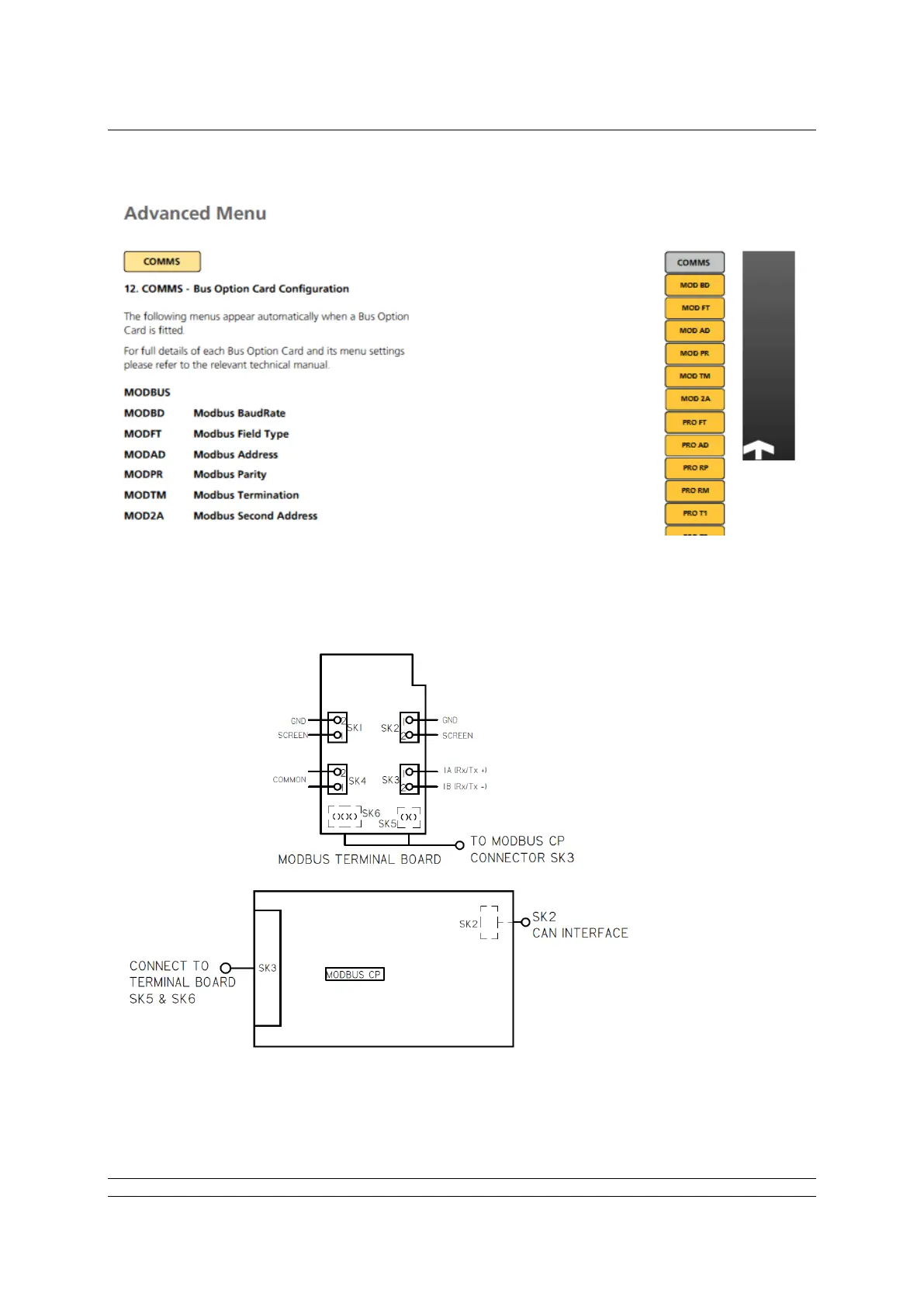
Fig 8: CMA menu structure for setting up the actuator: from the COMMS setting,
select the Modbus button. From here, you can adjust the individual Modbus settings.
Fig 9: Connections to the MFU located in a CMA actuator

Table of Contents

Related product manuals