Contents
Publication PUB091-004-00_0918 5 of 64
Table of Figures
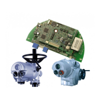
Fig 1: The Modbus Module Option Card Actuator Compatibility ..................................................... 7
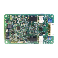
Fig 2: The Modbus Field Unit .......................................................................................................... 9
Fig 3: The MFU and its location behind the control module in an IQ3 .......................................... 11
Fig 4: The MFU located on the underside of the control PCB in a CVA actuator ......................... 13
Fig 5: The MFU located in a CMA actuator ................................................................................... 14
Fig 6: CMA menu structure for setting up the actuator: start at the BASIC setting ....................... 15
Fig 7: CMA menu structure for setting up the actuator: from the ADVANC setting, ..................... 16
Fig 8: CMA menu structure for setting up the actuator: from the COMMS setting,....................... 17
Fig 9: Connections to the MFU located in a CMA actuator ........................................................... 17
Fig 10: The MFU located in a K-Range actuator ............................................................................. 18
Fig 11: Typical RS-485 Data Highway ............................................................................................ 19
Fig 12: RS-485 Data Highway Topology ......................................................................................... 20
Fig 13: Typical RS-485 cable .......................................................................................................... 21
Fig 14: Active Termination for RS-485 highway. Biasing resistor values are typical. ..................... 22
Fig 15: Input and Output Data Direction .......................................................................................... 25
Fig 16: IQ3 Control Priorities ........................................................................................................... 29
Fig 17: Modbus transaction format .................................................................................................. 41
Fig 18: Limited Range Position Control and Reporting ................................................................... 55
Fig 19: Deadband and Hysteresis settings...................................................................................... 56
Glossary of Terms:
Address The unique address for a node on a particular highway of the fieldbus.
The address range is 1-247.
Enlight A graphical user interface for Bluetooth communication with CVA
actuators. This is downloadable from the Rotork web site,
www.rotork.com
Fieldbus The digital, two-way, multi-drop communication links.
Field Unit The Modbus Mk 3 option card fitted to the actuator.
Insight2 A graphical user interface for communication with IQ3, SI
3
and CVA
actuators. This is downloadable from the Rotork web site,
www.rotork.com
Interoperability The capability for a device from one manufacturer to interact with that
of another manufacturer, on a fieldbus network, without loss of
functionality.
Master/Slave Method of communication used by the Modbus Module. The fieldbus
requires a Modbus master to control the data exchange on the
highway.
Modbus The communication protocol used for data exchange, as defined in
IEC 61850.
Modbus RTU The version of the protocol used by the Rotork module.
Node A single device on the fieldbus.
Parity Bit added to data for error detection.