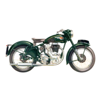
ROYAL ENFIELD 350cc O.H.V. WORKSHOP MANUAL
Page 4
Fig.
No. ...................................................................................... Page
Engine. Exploded View ... ... ... 2
1 Method of Removal of Valve End Caps ............... ... 7
2 Use of Terry Type Valve Spring Compressor 7
3 Bench Type Valve Spring Compressor ................ ... .... . 7
4 Tool for Removing Old and Inserting New Bush in
Connecting Rod .................... ... ....... ... ....... ... ....... 8
5 Correct and Incorrect Cutting of Valve Seats .................. 8
6 Detail of Joints in Push Rod Enclosure Tubes ................. 9
7 Valve Timing Marks ............ ... ....... ... ....... ... ....... ... ....... 9
8 Loosening Magneto Pinion ............. ... ....... ... ....... ... ....... 10
9 Adjusting Tappets ................ ... ....... ... ....... ... ....... ... ....... 10
10 Engine Sprocket Extractor .............. ... ....... ... ....... ... ....... 10
11 Clutch Centre Extractor .................. ... ....... ... ....... ... ....... 11
12 Engine Ready for Removal from Frame...... ... ... ... ......... 11
13 Pump Worm Extractor .................... ... ....... ... ....... ... ....... 12
14 Flywheel Assembly jig ................... ... ....... ... ....... ... ....... 12
15 Dismantling Flywheels in Vice ....... .......... ... ....... ... ....... 12
16 Separating Flywheels ........... ... ....... ... ....... ... ....... ... ....... 13
17 Test Bars and Gauge for Checking Connecting Rods
for " Bend " ................ ... ....... ... ....... ... ....... ... ....... 13
18 " Knife Edges " for Testing Connecting Rods for
" Twist " ..................... ... ....... ... ....... ... ....... ... ....... 14
19 Assembling Flywheels in Vice .................. ... ....... ... ....... 15
20 Drift for Removing Timing Side Bush and Roller
Race ................ ... ....... ... ....... ... ....... ... ....... ... ....... 15
21 Mandrel for Fitting Crankcase Main Bearings ................. 15
22 Use of Mandrel for Fitting Crankcase Main Bearings ....... 15
23 Feed Pump ................ ... ....... ... ....... ... ....... ... ....... ... ....... 16
24 Return Pump ............. ... ....... ... ....... ... ....... ... ....... ... ....... 16
25 Oil Circulation Diagram ................. ... ....... ... ....... ... ....... 17
26 Ball Valve in Oil Return Passage ... ....... ... ....... 17
27 Tool for Lapping Pump Discs ... ....... ... ....... 18
28 Detail of Felt Oil Cleaner ................ ... ....... ... ....... ... ....... 18
29 Removal of Gear Box End Cover .............. ... ....... ... ....... 19
Fig.
No. ...................................................................................... Page
30 Section Through Gear Box ............. ... ....... ... ....... ... ... 20
31 Drift for Removing Gear Box Ball Race ............... ... ... 21
32 Drift for Removing Gear Box Cover Ball Race ..... ... ... 21
33 Drift for Refitting Gear Box Ball Race ................. ... ... 21
34 Drift for Refitting Gear Box Cover Ball Race ....... ... ... 21
35 Detail of Foot Gear Change ....................... ... ....... .. .... 22
36 Adjustment of Clutch Control .................... ... ....... ... ... 22
37 Drift for Refitting Rear Hub Bearings .................. . . 24
38 Drift for Refitting Front Hub Bearings .................. ... 24
39 Detail of Fork and Steering Head Adjustments 26
40 Section of Amal Carburettor ...................... ... ....... ... ... 28
41 Contact Breaker Mechanism Cover Removed ... ... 29
42 H.T. Pickup ............... ... ....... ........... ... ....... ... ....... ... ... 29
43 Assembly of Felt Gland on Magdyno Spindle ... ... 29
44 Detail of Magneto Earth Brush .................. ... ....... ... ... 30
45 Exploded View of Magneto ....................... ... ....... ... ... 30
46 Use of Jig for Magneto Slipping Clutch ... ... 30
47 Tool for Removing Magneto Armature Bearings ........ 31
48 Mandrel for Replacing Magneto Armature Bearings .... 31
49 Contact Breaker Body and Tappet ... ....... ... ... 31
50 Contact Breaker End Plate ... ....... ... ... 31
51 Magneto Slipping Clutch ................ ... ....... ... ....... ... ... 32
52 Wiring Diagram ................... ........... ... ....... ... ....... ... ... 33
53 Connections to Voltage Regulator ... ....... ... ... 34
54 Exploded View of Dynamo ... ....... ... ... 35
55 Undercutting Mica .......... ...... 35
56 Testing Brush Springs for Tension 35
57 Commutator and Brush Gear ... ... ... 35
58 Voltage Regulator Adjustments ... ... ... 37
59 Headlamp. Reflector partially Removed ... 38
60 Tail Lamp. Cap Removed ... ... ... 38
61 Electric Horn ... ... ... ... ... .. 39
Lubrication Chart ... ... ... ... ... 40
ILLUSTRATIONS IN SUPPLEMENT.
62 Exploded View of Clutch ................................................. 42
63 Drift for Removing Driving Gear Bearing ....................... 43
64 Drift for Removing Mainshaft Ball Bearing .................... 43
65 Drift for Removing or Refitting Layshaft Bushes ............. 43
66 Burman Gear Box ............................................................ 44
67 Drift for Refitting Mainshaft Ball Bearing . 45
68 Drift for Refitting Driving Gear Bearing ... 45
69 Exploded View of Camshaft ... ... ... 46
70 Exploded View of Foot Change Mechanism ... 47
71 Exploded View of Kickstarter Mechanism ... 48
EVERY 2,000 MILES
Drain engine oil from tank and engine sump when warm, i.e.,
after a run, and refill. See Para. 26. On new and
reconditioned engines this operation must be carried out
after the first 500 miles.
Rear Chain. Remove for cleaning and attention. See Para. 34
EVERY 5,000 MILES
Engine Oil Filter. A new felt element must be fitted. See
Para. 26.
Gear Box. Drain when warm, i.e., after a run and refill to
correct level. See Para. 31. Drain plug is underneath
gearbox.
Chain Case. Drain chain case by unscrewing left foot rest nut
and pulling off foot rest and outer half of chain case.
Clean thoroughly, taking care not to allow oil to reach
rubber sealing band. Refit and fill up to level of overflow
plug. See Para 34.
Magdyno. Insert a few drops of light machine oil in the
lubricator in the end cap of the dynamo.
Magneto. The wick lubricating the contact breaker face cam
should be recharged with lubricant. See Para. 54.
Steering Head. The steering head races should be dismantled
and reassembled with fresh grease.
Brakes. These should be dismantled, cleaned and have the
operating cams greased. See Para. 42.
www.hitchcocksmotorcycles.com

 Loading...


