5.PANEL CONTROLS AND INDICATORS
5-1.Front panel(Fig. 4-1)
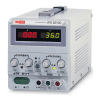
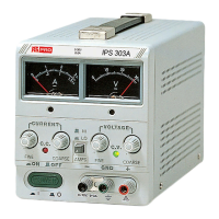
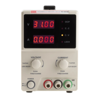
Lights when the power is on and in constant voltage operation.
Lights when in constant current operation.
For the coarse adjustment of the output voltage.
For the fine adjustment of the output voltage.
For the coarse adjustment of the output current.
For the fine adjustment of the output current.
Earth and chassis ground (Green).
Negative polarity (Black).
Indicates the output voltage.
Indicates the output current.
Current indicates HI/LO range selection.
5-2.Rear panel(Fig. 4-2)
With 115V or 230V voltage and current ranges selection (Refer to the
diagrammatic instruction to prevent mis-operating).
(18)
(19)
(20)
(21)
(22)
(23)
(24)
+ sense terminal
– sense terminal
+ output terminal
– output terminal
Ground terminal
Remote Control
OVP ADJ
OV
Screw type + sense input terminal.
Screw type – sense input terminal.
Screw type + output terminal.
Screw type – output terminal.
Screw type ground terminal (connected to case chassis).
Short or open the remote control terminal for output on or off.
Adjust trimmer VR401 to set the OVP value.